Introduction
A root loci plot is simply a plot of the s zero values and the s poles on a
graph with real and imaginary coordinates. The root locus is a curve of the location of the poles of a
transfer function as some parameter (generally the gain K) is varied. The number of zeros does not
exceed the number of poles.
The locus of the roots of the characteristic equation of the closed loop system
as the gain varies from zero to infinity gives the name of the method.
Such a plot shows clearly the contribution of each open loop pole or zero to the
locations of the closed loop poles. This method is very powerful graphical technique
for investigating the effects of the variation of a system parameter on the
locations of the closed loop poles. General rules for constructing
the root locus exist and if the designer follows them, sketching of the root loci
becomes a simple matter.
The closed loop poles are the roots of the characteristic
equation of the system. From the design viewpoint, in some
systems simple gain adjustment can move the closed loop poles to the desired
locations. Root loci are completed to select the best parameter value
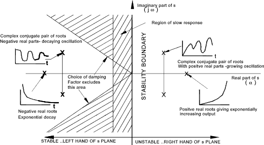
for stability. A normal interpretation of improving stability is when
the real part of a pole is further left of the imaginary axis.
Open and Closed Loop Transfer Functions
A control system is often developed into an equation as shown below
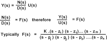
D(s) = (s - p 1).(s -p 2).. (s - p n)
is the characteristic equation for the system ...
m ≤ n
F(s) = 0 when s = z 1,z 2... z m..These values of s are called zeros
F(s) = infinity when s = p 1, p 2....p n...These values of s are called poles..
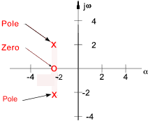
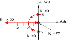
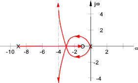
Below is shown a root loci plot with a zero of -2 and poles at (-2 ± 2 j ω ).
In practice one complex pole /zero always comes with a second one mirrored around the real axis
The Transfer function F(s) can also be written in polar form using vectors (modulus-argument ).
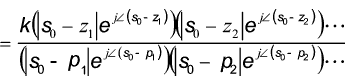
The complex numbers in polar form have the following elementary properties..
|z 1 .z 2 | = |z 1 |.|z 2 |.......&......|z 1 / z 2 | = |z 1 | / |z 2 |

A typical feedback system is shown below

The open-loop transfer function between the forcing input R(s) and the measured output Y1(s) =
Let G(s) = Q(s)/ P(s) and H(s) = W(s) /V(s) that is G(s)H(s) = Q(s).W(s) / P(s).V(s)
Then the open loop poles are the roots of the characteristic equation for the open loop transfer function.
The open loop zeros are roots of the W(s) Q(s)
The closed-loop transfer function =
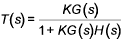
K is the value of the open loop gain .
1 + KG(s)H(s) is the characteristic equation
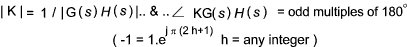
The closed loop poles ( when T(s) = infinity ) must satisfy
K.G(s).H(s) = -1
This is can be interpreted using vectors
Again letting G(s) = Q(s)/ P(s) and H(s) = W(s) /V(s) that is G(s)H(s) = Q(s).W(s) / P(s).V(s).
Then K(G(s).H(s) = -1 can be rewritten as K.Q(s).W(s) = - P(s)V(s) ....Therefore
The closed loop poles are roots of the characteristic equation for the closed loop system =
|
P(s).V(s) + K.Q(s)W(s) = 0
|
Generally the location of these roots in the s plane changes as the gain factor K is altered.
The root locus is the locus of these roots as a function of K.
For K = zero the roots of the above equation are roots of the P(s).V(s) which are the same as the poles of the
open loop transfer function G(s)H(s). If K becomes very large the roots approoach those of Q(s).W(s) which are the open-loops
zeros. Therefore as K is increased for zero to infinity the loci of the closed-loop poles originate from the open-loop poles
and terminate at the open loop zeros. If there is less zeros than poles then the some root loci originate
at open-loop poles
and increase towards infinity as K increases towards infinity.
Examples
Example 1
Consider system as diagram above with G(s) = 1/ s(s+2) , H(s) = 1
( P(s) = 1, V(s) = s(s+2), Q(s) =1, W(s) = 1)
The closed loop characteristic equation = s 2 + 2s + K = 0
The roots of the characteristic equation
When K = 0 , the poles at s = 0, and s = -2
When K = 1, the pole is at s = -1

The relevant root locus is shown below
Example 2
Consider system as diagram above with G(s) = 2s / ( s 2+1) , H(s) = 1
P(s) = (s2 + 1) , V(s) = 1 , Q(s) = 2s , W(s) = 1 )
The closed loop characteristic equation = P(s).V(s) + K.Q(s)W(s) = 0
therefore s 2 + 2Ks + 1 = 0
The roots of the characteristic equation
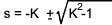
When K = 0 , the poles at s = + j , and s = - j
When K = 1, the pole is at s = -1

The relevant root locus is shown below
The system has the best stability point at K = -1, at values below this root loci moves
towards the instability boundary.
Rules for Constructing Root Loci
These rules are listed with minimum clarification..For more details refer to reference
links and reference texts..
The rules below are simple rules which obviate the need to completely solve the characteristic
equation allowing the methods to be used for relatively complex systems. The rules are based
on those devised by R.Evans in an important paper in 1948. They are
therefore known as Evans Rules. The rules only relate to positive changes in K.
For negative values of K a set of similar rules are used.
The closed loop poles are roots of the characteristic equation for the closed loop system =
P(s).V(s) + K.Q(s)W(s) = 0
This can be more clearly expressed as
Poles(s) + K Zeros(s) = 0
1) Number of root loci.(branches)
The number of root loci is equal to the order of the characteristic equation .
This is, for rational systems, the same order as the characteristic
equation for the open loop transfer function i.e. P(s).V(s)
2) Symmetry of loci
The roots of the characteristic equation having real coefficient are symmetrical with respect
to the real axis
3) Poles
The poles of lie on the root loci and correspond to K = 0. i.e roots of P(s).V(s) = 0
4) Zeros
The zeros lie on the root loci and correspond to K = infinity. i.e roots of Q(s).W(s) = 0 .
If there are "t" more poles than zeros then "t" loci will become infinite as K approaches infinity
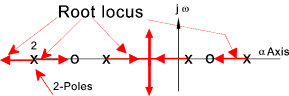
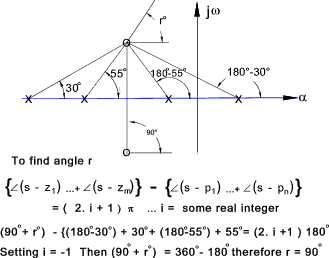
5) Asymptotes of root loci
If F(s) has "t" more poles than zeros, the root loci are asymptotic to "t" straight
lines making angles..
(2 b + 1)π / t,
b = 0,1,2,...t-1,
with the real axis . The root loci approach ssymptotes when K -> infinity..
| Asymptote angle with real axis for Poles - Zeros = t = 1 - 4 |
t= 1...Angle = π |
| t = 2...Angles = π / 2 ,3 π /2 |
| t = 3 ...Angles = π/ 3 , π, (5 /3) π |
| t = 4...Angles =
π / 4 ,
3 π /4 ,
5 π/ 4,
7 π /4
|
6) Point of Intersection of asymptotes
Asymptotes intersect on the real axis at a point with abscissa
so = (1/t). [(p1 + p2 + ...pn) - (z1 + z2 + ...zm)]
p's and z's are respective poles and zeros ofthe characteristic equation.
7) Root loci on real axis
If F(s) has one or more real poles or zeros ,then the segment of the real axis having
an odd number of real poles and zeros to its right will be occupied by a root locus.
8) Singularity/Breakaway Points
Singular points ( αb ) indicate the presence of multiple characteristic roots, and occur at
those values of s which for which dK/ds = 0..These points can also be obtained by solving the equation.
(- pi and - zi are the poles and zeros respectively)
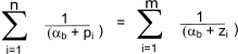
(-pi and -zi are the poles and zeros respectively)
Singularity /breakaway points ( αb ) occur where two or more branches
of the root-locus depart from or arrive at the real axis.
9) Intersection of root loci with imaginary axis
The intersections of root loci with the imaginary axis can be located by calculating the
values of K which result in the imaginary characteristic roots.
10) Slopes of root loci at complex poles and zeros
The slope of a root loci at a complex pole or zero of F(s) can be found at at point in the
neighborhood of the pole or zero using the method shown below
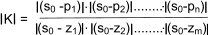
11) Calculation of K on the root loci.
The absolute magnitude of the value of K corresponding to any point so on a root locus
can be found by measuring the lengths of the vectors drawn to so from the poles and zeros of F(s) and
then evaluating
Examples of using Evans rules
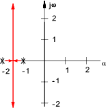
Example 3)
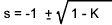
Consider the system with the open loop transfer function ( K > 0 & H(s) = 1 )
H(s)G(s) = K / (s2 + 3s + 2 ) = K / (s+1) (s+2)
Solving the Characteristic equation
Assuming negative feedback the characteristic equation =
s2 + 3s + 2 + K = 0
The Roots = [-3 ±
√(9 - 4(2 + K)) ] / 2 = -1.5 ± √(0.25 -K )
The plot below is simply obtained by establishing the roots for values of K from 0 to infinity..
K = 0 ....s= -1, -2
K = 0.25 ....s= -1.5
K ->¥....s -> ± j¥
|
Using Evans rules
System characteristic equation =
1 + K /(s+1)(s+2) = 0.... therefore (s+1)(s+2) + K = 0
1) The order of the characteristic equation = 2 therefore 2 poles.
2) The roots are symmetrical wrt the real axis
3) Poles correspond to K = 0, pole at -2, & - 1
4) Poles correspond to K = infinity no zeros
5) The asymptotes angles... 2 more poles than zeros therefore
angles are π /2 & 3π /2
6) Point of intersection of the asymptotes with the real
axis
= (sum of poles - sum of zeros) / t = -1.5
7) The root loci lie to the left of the odd pole. (first pole)
8) Location of a singularity is at dK/ds = 0 = -1.5.
9), 10) & 11) Not necessary.
The plot below can easily be obtained..
|
Example 4).
System has an open loop transfer function
K.G(s).H(s) = K (s + 1) / ( s2 .(s + 9))
closed loop characteristic equation i ..1 + K.G(s)H(s) = 0 therefore
s3 + 9s2 + K(s) + K = 0
Completing Evans Method.
1) There are three roots.
2) The characteristic equation has real coefficients so the loci is symmetrical about
the real axis.
3) When K = 0 there is a double pole at s = 0 (singular point) and also a pole at s = -9
4) When K = infinity there are loci at s = -1 (zero) and s = infinity.
5) The asymptotes angles... 2 more poles than zeros therefore
angles are π /2 & 3 π /2
6) The location of the asymptotes intersect the real axis is calculated by .. ( 0 - 9 - (-1) ) /2 = 4
7) Loci are to the left of odd poles/zeros's i.e left of -1 (between -1 & -9)
8) The break point (singularity point on the real axis ) is obtained by determining
the value of s which satisfies the equation dK/ds = 0..
Solving the closed loop
characteristic equation for K =
K = - (s3 + 9s2) / (s+1)
Differentiating (using du/dv = (vdu-udv)/v2 )
(s3 + 9s2)-(s+1)(3s2 +18s) = 0
...Therefore.. -2s3 - 12s2 -18s = 0 ... and.. -2s(s+3)2 - 0
Three solutions for s are at s = 0, s = -3 These are associated with a positive value
of K when substituted into F(s).
9) A Routh array is constructed to determine the imaginary axis crossing points. ref Routh Stability Criteria
| | Col 1 | Col 2 | Col 3 |
| Row 0 | s 3 | 1 | K | 0 |
| Row 1 | s 2 | 9 | K | 0 |
| Row 2 | s 1 | K | 0 | |
| Row 3 | s 0 | K | | |
There is no sign change in column 1 for positive values of K so there is locus does
not enter the right hand side of imaginary axis..
10 ) Rule not needed for this example..
The root locus plot is produced for this system as shown below...
Closed Loop Transient Response
The transient response of a closed-loop system is closely related to the
location of the closed loop poles.
Many control systems can be represented by the general second order differential equation..
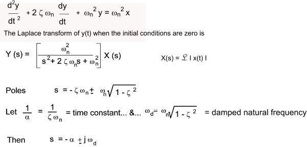
The coefficient (assumed positive) ωn is the undamped natural frequency
and ζ is the damping ratio.
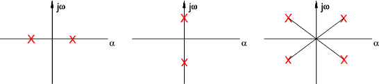
- If ζ > 1 Then both poles are negative and real
- If ζ = 1 Then both poles are equal,negative and real ( s = - ω n)
- If 0 < ζ < 1 The poles are complex conjugates with negative real parts.
s = -ζω n ± j ω n.Sqrt( 1 - ζ 2 )
- If ζ = 0 Then both poles are imaginary and
complex conjugate s = ± j ωn
- If ζ <0 Then both poles are in the RHS of the plane
|
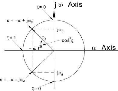
The results of this equation can be shown on a s plane plot as below..
|