Introduction
The induction motor is the most common type of motor. An induction motor consists of
a rotor and a stator. The rotor is mounted on bearings and rotates inside the stator
and is separated from the stator by an airgap.
In all electric motors (a.c and d.c) the torque is produced by the interaction of an
electo-magnetic field in the air gap between the fixed stator and the rotating
parts of the motor. However only with the a.c. motor is it possible for the
rotor current concerned to be produced by induction without any conducting path
by which the current can be supplied from outside.
In induction motors, whether single phase of polyphase, the windings on one part
(usually the stator)are supplied from an outside source. The current
is induced the other part, usually the rotor, the windings and the field produced
by the excited windings. Single phase motors are not self starting
unless special steps are made to make them so. They will run once
started but must be started by some device which turns them during the start-up
period. Three phase motors are self starting. The single
phase motor is only used on larger sizes when three phase supplies are not
available.
The notes below relate mainly to polyphase induction motors.
Notation -for factors used in rotating loop equations
A = Area of loop (m2 ) = w.l = w.2.r
B = Flux density (Tesla)
e = instantaneous e.m.f. (V).
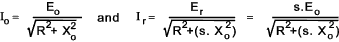
E o = rotor e.m.f.(V) generated per phase at standstill
E r = rotor e.m.f. (V) generated per phase at unit slip = s (rotor frequency fr=sf
f = Supply frequency (herz)
f r = frequency of rotor e.m.f = (herz = cycles/sec)
I = R.M.S. value of alternating current (amperes)
I max = maximum value of alternating current (amperes)
Io =the rotor current at standstill (amperes)
Ir = rotor current per phase(amperes) at slip s.
l = length of rotating loop (m)
M = Torque transmitted to rotor (N.m)
r = radius of rotating loop (m)
R = the resistance per phase (Ω)
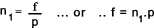
n 1 = speed of rotating flux (rev/s)
nr = speed of rotor (rev/s)
N = Number of windings
p = number of pole pairs
V = R.M.S. value of alternating voltage (Volts))
V p = Voltage/phase applied to stator winding (Volts)
w = width of rotating loop (m) = 2.r
Xo = the leakage reactance per phase at standstill (Ω)
Zs = number of stator winding in series per phase
Φ = Flux (webers)
ω = Angular velocity of loop (rads/sec) = 2πf
φ = phase difference (radians)
|
Motors
The induction motor is the most common type of motor. An induction motor consists of
a rotor and a stator. The rotor is mounted on bearings and rotates inside the stator
and is separated from the stator by an airgap.
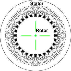
The stator core is made up of laminations along its length and includes
numerous axial slots in which are embedded conductors. The conductors are interconnected in such a way
so as to produce rotating fields when AC current flows through them.
The rotor of an induction machine is cylinderical and generally conforms to one of two alternative
designs as shown below
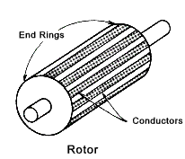
1)(Cage-Type /Squirrel Cage type). It can have a number of radially space conducting bars short circuited at both
ends by conducting rings .
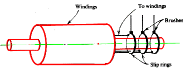
2)( Wound-rotor machine) It can have polyphase windings - three phase as shown-with terminals brought out to slip rings for
external connections . Normally the three phases are connected together at one end and connected to slip rings at the other. A three phase variable
resistance is connected across the slip rings. This resistance serving to reduce current at starting and it can be used
to control the speed when running.
Production of a rotating field
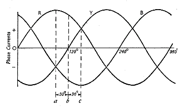
Initially consider a stator working on a two phase supply wired for two poles as shown.
The current flow though the conductors A-A1 and conductors B-B1
are shown and it is clear that the induced lines of flux are rotating clockwise as a result of the alternating currents.
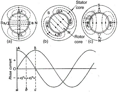
At (a) there is maximum current
and therefore maximum induced magnetic flux is coil A-A1 with zero current in B-B1 with zero induced magnetic flux
At (b) the current in conductors A-A1 and loop B-B1 is 0,707I max the associated magnetic flux
is equal as shown. At (c) the current in B-B1 is Imax and the current in A_A1 is zero
the associated induced magnetic flux varies the same.
It may be seen that the poles complete a full rotation over on complete cycle. If the machine has
p pairs of poles , the resulting magnetic flux rotates through 1/p revolutions in 1 cycle.
If the supply frequency was f (Hz) then the speed of the magnetic flux would be f/p
Considering a stator working on a three phase supply wired for two poles as shown.
The current flow though the conductors A-A1, R-R1 and Y-Y1 are shown and it
is clear that the induced lines of flux are rotating clockwise as a result of the alternating currents.
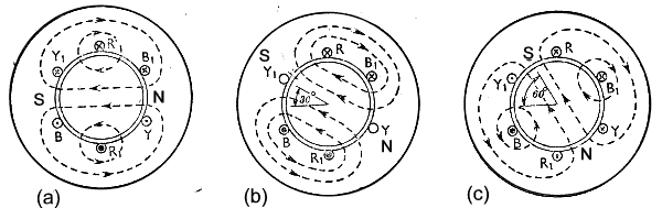
It may be seen that the poles complete a full rotation over on complete cycle. If the machine has
p pairs of poles , the resulting magnetic flux rotates through 1/p revolutions
in 1 cycle. If there were 2 pairs of poles the field would rotate through 1/2 revolutions per cycle.
As for the 2 phase system considered above. The rotational speed of the magnetic field n =
Principle of the induction motor..
First considering the cage-type rotor. The rotor core is generally laminated and consists of uninsulated copper or alumninium bars
in axial slots. The bars are short circuited at each end by rings or plates...
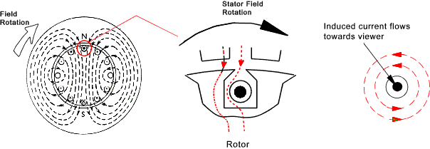
In the above figure it is shown that the field is rotating clockwise relative to the rotor conductors.
The results in an induced current flowing towards you as shown. (Application of Flemings Right Hand Rule).
The induced current caused a magnetic field to be set up as shown on the right hand figure. This reinforces the
rotating field on the left of the conductor and reduces the field on the right. There is
thus a clockwise force on the conductor. The force is clearly the greatest when
the flux is moving fastest relative the conductor . If the rotor accelerates up to the speed
of the rotating field there will be no induced current and no resulting force....
For any torque within the rating of the motor there is degree of slip.
Per-unit Slip = s = (Synchronous Speed - Rotor Speed) / Synchronous Speed = (n 1 - n r )/ n 1
Percentage slip = per-unit slip .100
The value of percentage slip at full motor load varies from about 6% for small motors to about
2% for large machines
Speed of induced e.m.f /current in rotor
The speed of the rotating flux is n 1 revs/s = f /p
If n r is the rotor speed then the speed at which the rotors are being
cut by the flux is (n 1- nr) revs/s.
The frequency of the rotor e.m.f f r = (n 1- n r) p.
If s (per-unit slip) = (n 1- n r) /n 1 then n 1- n r = s.n 1 Therefore
f r = s.n 1p = sf
The current in the rotor conductors caused by the rotating induced
e.m.f produces a resultant magnetic field with a axis which rotates at a speed
s.n 1 relative to the rotor surface in the same direction as the rotor
rotation.
The speed of the resultant rotor magnetic field relative to the stator core is .
s.n 1 + n r = n 1 - n r + n r = n 1
The rotating rotor field m.m.f is stationary relative to the rotating stator m.m.f. A polyphase induction
motor is equivalent to a transformer have an air gap separating the magnetic circuits carrying the primary and
secondary windings..
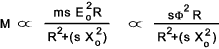
Rotor e.m.f and current
V p = Voltage/phase applied to stator winding (Volts) and
Zs = number of stator winding in series per phase.
Let E o = rotor e.m.f.(V) generated per phase at standstill and also let
E r = rotor e.m.f. (V) generated per phase at unit slip = s (rotor frequency fr= sf then
E r = s E o
If R is the resistance per phase of the rotor winding and
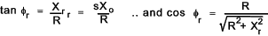
Xo = the leakage reactance per phase
of the rotor winding at standstill = 2(π)f x leakage inductance /phase of rotor winding.
Then for a slip s the relating reactance per phase = Xs =sXo
.The corresponding impededance per phase is
Z r = √ [ R 2 + (sXo)2]
If Io =the rotor current at standstill and Ir = rotor current at
per phase at slip s.
If φ is the phase difference between the Er and Ir then
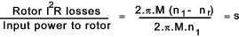
Power Lost to rotor
If the rotating stator flux is rotating at n 1 revs/s and
the rotor is rotating at n r revs/s. and the torque transmitted
to the rotor = M then the power losses in the rotor which are primarily the I2 R losses
= M. 2.π.( n1 - nr ) therefore..
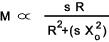
Torque considerations
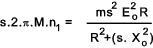
The electrical power generated in the rotor = m.Ir.Er.cosφr. ...
m is the number of rotor phases and cos φ is the power factor. This is equal to

This power is dissipated as I2R losses in the rotor system.
The input power to the rotor
is = 2.π.M.n1 and therefore from the equation above.
Thus for a set synchronous speed and number of rotor phases.
If the impedance of the stator windings is assumed to be negligible , the for a given supply
voltage Φ and Eo are constant. Therefore
The figure below shows a number of performance curves for a polyphase inductive motor. The curves reasonably reflect
the values of the above equation over a range of s values R, and Xo values.
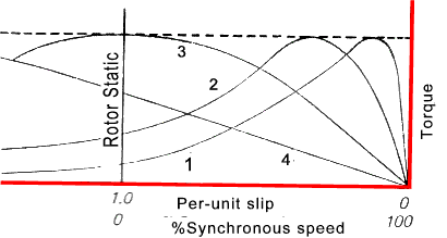
Assume Xo = 10 Ω for all curves
Curve 1 shows a typical cage type motor or one with the rotor circuits short-circuited.
(Say R = 1 Ω )
at values of s < 0,1 (say) the (s.Xo)2 will be very small and M will be proportional to s/R.
At larger values of s (sXo)2 will be larger than the R2 term and therefore as Xo is constant M will be proportional to R/s
Curve 2 shows a typical wound-rotor motor with a higher resistance in the rotor circuit. (say 2.Ω )
Curve 3 shows a typical wound-rotor motor with a medium resistance in the rotor circuit (R = 10 Ω= X)
Curve 4 shows a typical wound-rotor motor with a high resistance in the rotor circuit say 25.Ω ..M will be roughly proportional to s / R
The maximum torque achieved for all curves is when the Resistance R = sXo.
Induction Motor Operations
Motors with cage type rotors have low starting torques and maximum torques at low slips i.e. at near synchronous speeds. These are low cost
units with very good performances if it is acceptable to have low starting torques.
Motors are available with special designs to compensate for this problem, e.g dual
rotor types, at
higher costs. Cage rotor type motors also require a high starting current which can result in undesireable surges.
For this reason these motors are mainly used for lower duty applications.
When used for higher duties the starter controls include methods of
reducing the voltage at start-up. e.g start-delta starting or using
an autotransformer.
Slip ring induction motors starter systems generally include star connected sliding
resistances which are connected at start-up such that the maximum starting torque is achieved.
As the motor accelerates the contacts progressively slide over the resistances such that
at maximum speed the connected resistance is zero. Using this comparatively low cost control
system the starting torque is maximised with a comparatively low starting current. Also the operating
torque is maximum at low slip providing good efficiency.
All induction motors and particularly cage-type motors have low power factor at low loads,
and the small motors have low power factors at all loads.. The power factors are
worse for motors with sleeve type bearings compared to motors with rolling bearings.
Using motors which are too large for the connected loads results in continuous low power factor operation with the consequent
cost penalty
Typical Efficiencies of Polyphase Induction Motors
| Output kW | 1 | 5 | 10 | 20 | 50 | 100 | 200 | 300 |
| Efficiency % | 80 | 85 | 86 | 88 | 89 | 90 | 92 | 93 |
|