Electrics Index ElectroMagnetism
Introduction.....
Nomenclature.....
Conversions.....
Magnetic induction.....
Magnetic Field Due to an electric Current....
Force on a conductor in a magnetic Field .....
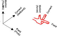
Flemings Left Hand Rule.....
Electromagnetic induction.....
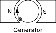
Flemings Right Hand Rule.....
Magnitude of induced current.....
Magnetic circuits.....
Comparing magnetic and electric circuits.....
Comparing electromagnetic and electrostatic names.....
|
Introduction Basic Notes on Magnets
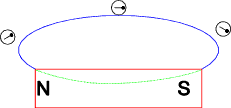
If a permanent magnet is suspended, so that it is free to swing in a horizontal plane, it
will take up such a position that one end will point towards the north pole. This
end is said to be the north-seeking end of the magnet. The other end of the magnet
is called the south seeking end. Therefore the earths north pole is actually its south magnetic pole
Lines of magnetic flux never intersect.
Nomenclature
I = current flow (amperes) Conversions In older textbooks values are given in (CGS) units . Below are a small number of useful conversions .
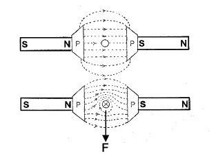
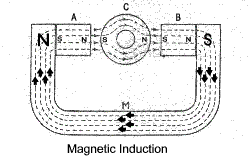
Magnetic Induction If a soft iron block is located within a magnetic field the lines of flux will pass through the iron block and it will become a temporary magnet. The iron block is magnetised as a result of magnetic induction. The figure below shows a U shaped permanent magnet with two soft iron blocks (A & B) attached to the magnet and a cylinderical block C located between A & B. No lines of magnetic flux pass through the hole in the cylinderical block and any object placed in this hole would be screened from the magnetic field.
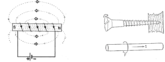
Magnetic Field Due to an Electric Current When a conductor carries an electric current a magnetic field is produced around that conductor.
When a conductor is formed into a solenoid the resulting magnetic field formed is as shown in the figure below. The relationship between the current flow around a solenoid and the magnetic field is identified using the right hand rule.."If the right hand grips the outside of a coil with the fingers in the direction of the current flow the thumb points in the direction of the magnetic field in the centre of the solenoid."
Magnetic Force on a Conductor in a magnetic field When a conductor carrying an electric current is located in a magnetic field the lines of flux generated by the current are opposed to the fixed field at one side and they combine with the fixed field at the other side. The result is that there is force on the conductor as shown in the figure below..
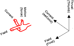
The force on a conductor in a magnetic field is related to the current and is also related to the strength of the magnetic field. Flemings Left Hand Rule. This is used to identify the relative directions of the field, current and motion (Thrust) when a current flows in a conductor in a magnetic field........
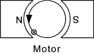
Applying this to an electric motor..
The definition of flux density (Flux Density) is such that the force on a conductor of length l in a magnetic field of flux density B webers when the current flow in the conductor is I amperes is F (newtons) = I.l.B Electromagnetic Induction In 1831 Michael Faraday discovered that if a conductor moves relative to a field of magnetic flux a current flow is induced in the conductor. The magnitude of the induced current is related to the strength of the magnetic field and to the velocity of relative motion. Consider a negative charge (-q )moving towards the left in a downward direction magnetic field which is equivalent to a current ( I )in the opposite direction . Both experience a force as shown in the figure below. In the same way a positive charge (+q ) moving to the left which is equivalent to a current I moving in the same direction will experience a force in the opposite direction.
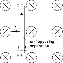
Now consider a conductor moving towards the left at a velocity of v. The electrons will experience a force F tending to move them up leaving positive ions at the other end of the conductor. This movement will continue until the force F moving the charges is balanced by the resulting e.m.f opposing the motion.. ref, Def. Flux Density
If the length of the conductor is l then the work done in moving a unit charge Q along the conductor is W = Blv This is equal to e.m.f along the conductor of...E = Blv In general the e.m.f generated in a conductor moving in an electric field is
Faraday's Laws..Faraday educed two laws 1) While the magnetic flux linking with a circuit is changing,
an e.m.f is induced in the circuit. Lenz's Law is stated as follows. "The direction of induced e.m.f is always such that it tends to set up a current opposing the motion or the change of flux responsible for inducing that e.m.f". Flemings Right Hand Rule This identifies the relative directions of the induced current,field and motions..
Applying this to an generator..
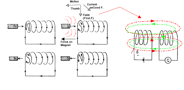
Magnitude and Direction of Induced Current A magnet moving into a coil induces current flow as shown. A similar condition occurs with two adjacent coils when a current flow is initiated, as shown in red, in one of the coils. The magnetic field (shown in red) as it increases is similar to a magnet moving into the second coil induces an e.m.f resulting in a current flow flow as shown in green. This induced current flow results in a magnetic flux opposing the original flux as shown (in green). When the current flow in the primary circuit stabilises the flux is constant and the induced e.m.f in the secondary circuit becomes zero. If the switch is now opened the flux will collapse causing a current flow in the second circuit which tends to oppose the collapsing field.
Let the magnetic flux through a coil of N turns be increased by Φ webers
in t seconds as a result of the relative movement of a fixed magnet (or due
to the
generation of a field by initiating current flow in an adjacent coil). Since each line of flux cuts each turn of the coil then the average e.m.f induced in
each coil is Φ /t volts. Following lenz's law the current resulting from this e.m.f tends to
prevent the changing flux - it tends to set up an opposing flux. The result of this interaction is that
the coil tends to oppose the movement of the magnet.
From the above it is is possible to define a weber as the magnetic flux which linking a circuit
of one turn induces an e.m.f of 1 V when the flux is reduced to zero at a uniform rate in 1 second.
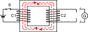
If the connected coil C1 has N 1 turns then the average e.m.f induced is
The direction of this e.m.f. (according to Lenz's law) is such
that it tends to oppose the growth of the current.
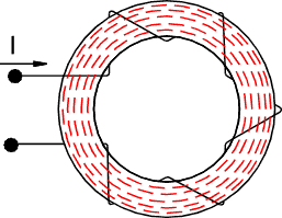
Again the e.m.f circulates a current which tends to induce a flux which opposes the flux that is induced by the rising current in coil C1... Magnetic Circuits The complete close path followed by any group of magnetic flux lines is called the magnetic circuit. In the sketch below the magnetic circuit is a steel toroidal ring with a coil which induces the flux when current flows.
A magnetic circuit has similar relationships to an electric
circuit. In an electric circuit the current flows due to the electromotive
force (e.m.f) while in a magnetic circuit the flux is due to the magnetomotive force m.m.f.
The m.m.f. is proportional to the current flowing and the number of turns and is called the Ampere Turns.
Dimensionally it is simply Amperes because turns is not really a dimension quantity.
The m.m.f is given the symbol F.
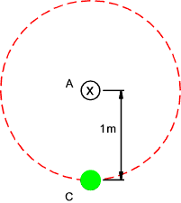
Consider a single conductor A carrying a current of 1 Ampere as shown with only the effects
of the current flow down being considered (the return flow path being some distance away). The magnetic field
strength at a radius of 1 m is 1 ampere(turn) and the length of the field is 2π.metres. The magnetic
field strength at 1m is therefore 1/(2.π) amperes(turns) per metre.
The ratio B/H for a vacuum is called the permeability of free space and is given the symbol μo with units
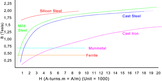
henry per metres and is virtually the same for a vacuum , air , and other non-magnetic materials such as wood, oil, copper etc μ = B/H μr for non magnetic materials is generally about 1. For ferromagnetic materials iron, steel etc μr varies significantly as H increases. To illustrate this point ref to figure below showing a very very approximate B/H curves for different ferromagnetic materials.
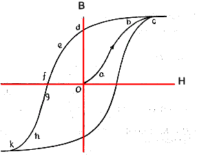
Hysterisis When considering ferromagnetic materials in electromagnets subject to alternating currents such as in electric motors and transformers it should be noted that the magnetic flux does not move up and down a single curve as the initiating electrical current rises and falls. In practice the magnetic flux follows a curve approximated by the figure below.
Initially the ferromagnetic material is unmagnetised
at 0 then, as H increases, the flux (B) follows the path a-b-c. At c the
material is effectively saturated. Now if H is reduced to zero degree of
magetism moves along the curve to d. Although the magnetising force has
reduced to zero the ferromagnetic material has retained a most of its magnetism. Analogy between Magnetic and Electrical Circuits
Comparison of Electromagnetic and Electrostatic Variable names and Symbols
| ||||||||||||||||||||||||||||||||||||||||||||||||||||||||||||||||||||||||||||||||||||
Useful relevant Links
|
|
Electrics Index

 >
>