Hydraulics (Hydrostatics )
Important: The notes below relate to the area of hydraulic identified as hydrostatics. In Hydrostatics
the Pressure energy of the fluid is converted into mechanical motion. This differs with the alternative area
known as Hydrodynamics whichi is concerned with the kinetic energy of the fluid. Hydrostatics is also generally based
on oil as the fluid although, in the recent past water was the prime fluid used.
Hydraulics are used for providing high torques and high forces with a high level
of control of the motion. Hydrualic fluid is virtually incompressible so
controlling the flow of fluid provides accurate control of the motion of the relevant
actuator..
Typical uses of Hydraulic drives include..
- Car braking systems
- Vehicle drives in agricultural and civil applications
- High power low weight motors (high speed and low speed)
- Elevators
- Aircraft motion control- wings - undercarriage etc
- Hydraulic Hoists
- Automation actuators
- Machine tool drives
- Flight Simulators- For training pilots
- Motion Simulators- For vibration seismic testing
|
The primary advantage of hydraulic systems compared to pneumatic and electric systems
is that high forces and torques can be developed with comparatively compact motors which
are very convenient for mountingin different locations and orientations.
Very accurate motion controls are possible using sophisticated servo valves and servo
controlled motors and pumps.
The disadvantages of hydraulic systems include the relatively high cost of components
and the need to condition and contain the hydraulic fluid and also the need maintain
the system ( regular filter changing /checking for leaks/ chaning oil).
The best examply of a simple, reliable bring system is in the braking system of all conventional cars
Depressing the brake pedal operates on the piston in the brake's master cylinder/s. Slave pistons,
one at each wheel,are then actuated to press the brake pads against the brake rotor to stop the car
Notes on Hydrostatic Drives are provided on webpage Hydrostatic Dives
Hydraulic system Components
Hydraulic systems are generally confined to local areas e.g. a vehicle, a machine tool. They are
not designed as distributed systems as are pneumatic systems. However large distributed
systems have been employed. In times past, in cities, very extensive systems have been engineered to serve
diverse hydraulic units elevators - bridges etc.
Hydraulic systems ...
Operating Conditions.
Hydraulic power systems systems use hydraulic fluids at pressures between 35 barg and 350 barg.
The hydraulic fluid must be maintained within safe temperature regime by natural radiation/convection or by use of coolers.
The hydraulic components have close clearances so the fluid must be filtered.
Suggested velocities in hydraulic systems are as follows.
- Pump Suction...0,6 - 1,2 m/s
- Delivery flow...2,0 - 5,0 m/s
- Return flow...1,5 - 4,0 m/s
|
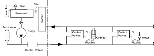
Power Pack
The hydraulic power pack impart the essential potential energy to the hydraulic fluid
using appropriate pumps e.g. Gear, Vane, Piston pumps are used. The power pack normally includes
the following features.
- Reservoir for hydraulic fluid - with instrumentation, air filter and strainer over outlet
- Protection for pump including filter
- Pump located below reservoir to minimise suction feed requirement
- Accumulator to maintain steady pressure against flow variations
- Cooler for removing waste heat from the system (Air cooler /Water cooler)
- Control valves, relief valve, unloading valve, isolation valves
- Provision for containing any leaks with suitable instrumentation
|
Typical power pack duties obtained from a suppliers literature
10 kW ....45 l/m......120 bar...3 kW Oil cooler
50 kW ....120 l/m.... 200 bar...15 kW Oil cooler
Interconnecting Pipework
The interconnecting piping on hydraulic systems feeds should include for pressurised piping
from the power pack to the equipment and also return piping from the equipment to the reservoir through
the cooler.
The interconnecting pipework is very important in hydraulic systems because it is
essential to have no fluid leakage against an environment with a high degree of
continuous vibration
Connections systems are available using compression fitting, O-ring fittings, and
at the highest level welded fittings. It is often necessary to include
flexible hoses connecting to the actuators . These are generally the most unreliable
part of the system and must be carefully designed in strict accordance with the
suppliers instructions
Hydraulic Valves
Hydraulic valves are generally highly engineered components. Valve types include
- Pressure Control Valves - e.g Relief valves, unloading valves, pressure maintaining valves
- Flow Control Valves -
- Direction Control Valves -
- Servo Valves - providing high accuracy fast response control of pressures and flowrates.
|
The control valves are often controlled using electronic /computer control systems...
Hydraulic Actuators
Hydraulic actuators generally based on single or double acting cylinders and motors.
Small cylinders of less than 10mm dia are available. At the other extreme hydraulic
press tools are available capable of forces in excess of 5000 te.
The motors can be low speed (less than 0.5 rpm ) through to high speed (more than
10,000 rpm). Motors can be provided with torque ranges for 1Nm (high speed)to 20000 Nm.(Low Speed)..
The diagram below is a very simplified generalisation of a hydraulic system circuit. The cooler
and the accumulator are shown although on the majority of applications these components may not be required

| 