Introduction
Normally a beam is analysed to obtain the maximum stress and this is compared to the
material strength to determine the design safety margin. It is also
normally required to calculate the deflection on the beam under the maximum expected
load. The determination of the maximum stress results from producing the
shear and bending moment diagrams. To facilitate this work the first
stage is normally to determine all of the external loads.
Nomenclature
e = strain
σ = stress (N/m2)
E = Young's Modulus = σ /e (N/m2)
y = distance of surface from neutral surface (m).
R = Radius of neutral axis (m).
I = Moment of Inertia (m4 - more normally cm4)
Z = section modulus = I/ymax(m3 - more normally cm3)
M = Moment (Nm)
w = Distrubuted load on beam (kg/m) or (N/m as force units)
W = total load on beam (kg ) or (N as force units)
F= Concentrated force on beam (N)
S= Shear Force on Section (N)
L = length of beam (m)
x = distance along beam (m)
Calculation of external forces
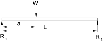
To allow determination of all of the external loads a free-body diagram is construction with
all of the loads and supports replaced by their equivalent forces. A typical free-body
diagram is shown below.

The unknown forces (generally the support reactions) are then determined using
the equations for plane static equilibrium.

For example considering the simple beam above the reaction R2 is determined by
Summing the moments about R1 to zero
R2. L - W.a = 0 Therefore R2 = W.a / L
R1 is determined by summing the vertical forces to 0
W - R1 - R2 = 0 Therefore R1 = W - R2
Shear and Bending Moment Diagram
The shear force diagram indicates the shear force withstood by the beam section along the length of the beam.
The bending moment diagram indicates the bending moment withstood by the beam section along the length of the beam.
It is normal practice to produce a free body diagram with the shear diagram and the bending moment diagram position below
For simply supported beams the reactions are generally simple forces. When the
beam is built-in the free body diagram will show the relevant support point as a reaction
force and a reaction moment....
Sign Convention
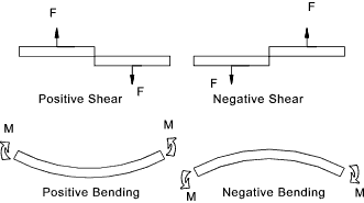
The sign convention used for shear force diagrams and bending moments is only important
in that it should be used consistently throughout a project. The sign convention
used on this page is as below.

Typical Diagrams
A shear force diagram is simply constructed by moving a section along the beam
from (say)the left origin and summing the forces to the left of the section.
The equilibrium condition states that the forces on either side of a section balance
and therefore the resisting shear force of the section is obtained by this simple
operation
The bending moment diagram is obtained in the same way except that the moment is the
sum of the product of each force and its distance(x) from the section. Distributed
loads are calculated buy summing the product of the total force (to the left of the section) and the
distance(x) of the centroid of the distributed load.
The sketches below show simply supported beams with on concentrated force.

The sketches below show Cantilever beams with three different load combinations.

Note: The force shown if based on loads (weights) would need to be converted to force units
i.e. 50kg = 50x9,81(g) = 490 N.
Shear Force Moment Relationship
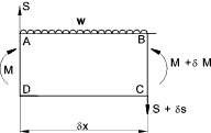
Consider a short length of a beam under a distributed load separated by a distance δx.

The bending moment at section AD is M and the shear force is S. The bending
moment at BC = M + δM and the shear force is S + δS.
The equations for equilibrium in 2 dimensions results in the equations..
Forces.
S - w.δx = S + δS
Therefore making δx infinitely small then.. dS /dx = - w
Moments.. Taking moments about C
M + Sδx - M - δM - w(δx)2 /2 = 0
Therefore making δx infinitely small then.. dM /dx = S
Therefore putting the relationships into integral form.

The integral (Area) of the shear diagram between any limits results in the change of the shearing force between
these limits and the integral of the Shear Force diagram between limits results in the change in
bending moment...
|