Machine_Parts_Index

Cam Design

More details on Cam design are to be found in the links below the table

INTRODUCTION

A Cam is a machine component that either rotates or moves back and forth (reciprocates) to create a prescribed motion in a contacting element known as a follower. The shape of the contacting surface of the cam is determined by the prescribed motion and the profile of the follower.

Cam-follower mechanisms are particularly useful when a simple motion of one part of a machine is to be converted to a more complicated prescribed motion of another part, one that must be accurately timed with respect to the simple motion and may include periods of rest (dwells). Cams are essential elements in automatic machine tools, textile machinery, sewing machines, printing machines, and many others. If the follower is not restrained by a groove on the cam, a spring is necessary to keep the follower in contact with the cam.

Cam systems can replace relatively complicated linkages in achieving desirable motion cycles.

In all cam systems it is important that the follower is always in contact and following the motion of the cam. This is achieved in a number of ways including the following.

  • Gravity
  • Using a mechanical constraint system i.e groove
  • Using a spring force
  • Using a pneumatic or hydraulic force

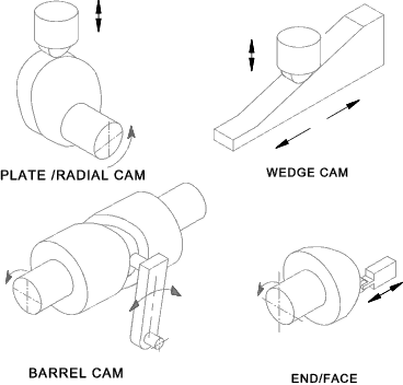
Cams are made in a variety of forms,including:

  • A rotating disk or plate with the radial required profile;
  • A reciprocating wedge of the required shape.
  • A cylindrical barrel cam with a follower groove cut in the diameter
  • A cylinder with the required profile cut in the end (end cam);

Cam followers

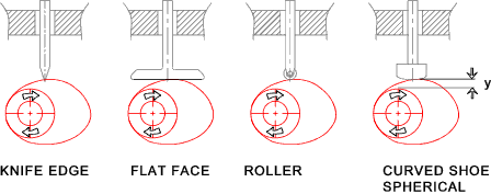
Cams followers can be either reciprocating or pivoting.   There are various methods of transferring the motion from the cam to the follower including the following:

  • Knife Edge
  • Flat-face
  • Roller
  • Curved-shoe /spherical

The cam follower can be either offset (as shown below) or in line with the cam centre of rotation..

Design of Cam Systems

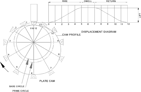
The first stage in designing a cam system is the creation of a displacement diagram... A typical plate cam with an in-line roller follower is shown below with a displacement diagram. This figure shows the following characteristic features.

  • The rise- This is when the follower is moving away from the cam centre.    The slope reflects the follower velocity
  • The dwell- the is the period when the follower is stationary
  • The return - This is when the follower moves back towards the cam centre
  • The base circle on the cam is the smallest full diameter of the cam
  • The prime circle is centered on the cam rotation centre with radius at the follower roller centre when the follower is on the base circle
  • The cam profile is the shaped surface of the cam defining the follower motion


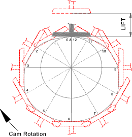
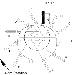
The diagram below shows a plate cam with a flat face follower showing twelve follower positions..


The diagram below shows a plate cam with an offset roller follower showing twelve follower positions..


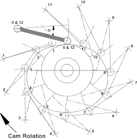
The diagram below shows a plate cam with an pivoting follower showing twelve follower positions..

Kinematic Coefficients of Cam

The displacement diagram is a plot of the cam displacement vs the cam angle e.g.    y = f(θ)
It is possible to plot additional graphs as follows

1) The First order Kinematic Relationship

f'(θ) = dy /dθ..

This is a plot of the slope of the displacement graph and thus the rate of movement of the follower.  High values of f'(θ) result in very steep cam slopes with a risk the the follower will jam


2) The Second order Kinematic Relationship

f''(θ) = d2y /dθ2..

This is related to the curvature of the cam. If f''(θ) becomes very large the curvature of the cam approaches zero ( a point). This is highly unsatisfactory as it results in very high contact stresses and consequent wear...


To be continued


Links to Cam Design
  1. R.D.Dane Coporation..Components
  2. Technology Students Site..Notes on Cam Types
  3. Cams ..Useful download on Cam Design
  4. Cam and Follower systems ..Educational animations
  5. Introduction to Mechanisms = Chapter 6 Cam Design ..Lots of very useful reference notes


Machine_Parts_Index