| |
Mechanism general notes
Escapement Mechanisms
More details on Escapement Mechanism design are to be found in the links below the table
|
Escapements
There are many forms of escapements often requiring some ingenuity in their
derivation. Escapements are gemerally used in clocks with mechanical
motions. When used with clocks the escapement controls the spring
driven clock mechanism such that it moves in regulated steps controlled by a
pendulum or an oscillating arm.
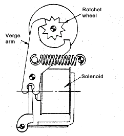
For the mechanism to operate correctly,one drive tooth must be at least partially retracted from
the ratchet wheel before the other drive tooth strikes the wheel. This lost motion is
undesireable since it means that the driver will acquire some kinetic energy before it starts to move
the wheel. In an inexpensive inverse escapement, and low cost is one of the principle
attractions of the device, indexing is accomplished by a series of blows or impacts
rather than by a series of smooth impulses. Nevertheless, this is a useful mechanism
for light and moderate power levels. Inverse escapements are used in
many electomechanical counters, and may be operated at speeds of 3000 cpm. Variations of the inverse escapement
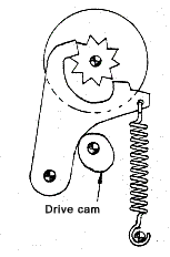
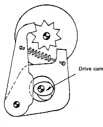
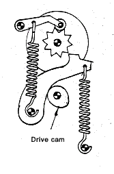
are illustrated below .
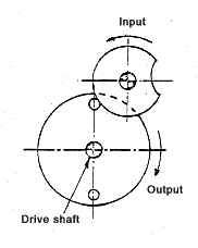
In the figure below the cam driver has been carried a step further by dividing the cam driver into two parts and using a double-level input cam. Each drive tooth can be controlled independantly of the other so tha impact is practically eliminated.
In the figure below one half of the drive arm has been replaced by a detent arm. This detent must index the wheel as well as position it,since if it did not move the wheel the powered arm would keep hitting the same wheel tooth and there would be no resulting motion
True escapements periodically release a force which drives a load.
The force is always trying to drive the load , but cannot do so until the escapement
allows. The main flow of power in ratchets and genevas, for example,
is through the intermittent motion mechanism: on the other hand an escapement,
which is a control device is operated at low power levels even when it is releasing
energy from a high-powered source.
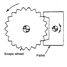
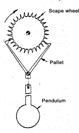
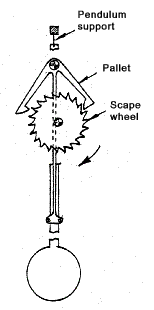
Runaway Escapement In the type of escapement shown below torque is applied to the scape wheel causing it to rotate.
One tooth of the scape wheel encounters on arm of the pallet and the pallet is pushed aside. Rotation
of the pallet in turn , frees this tooth, simultaneously bringing the alternate pallet arm into
interference position with a second tooth. The pallet and scape wheel are mounted on
close centres so that one arm or the pallet will always interfere with the motion of
the scape wheel. As the wheel rotates its movement is arrested by repeated (periodic) impact with the pallet.
Thus the wheel can rotate only when and as the pallet is free to oscillate.
Most contemporary timers are tuned escapements instead of runaways.
The runaway escapement output speed varies with applied torque but in a tuned
escapement speed is determined by a mechanical oscillator - a pendulum or an
oscillating spring-mass assembly . Input torque has little effect on
performance.
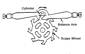
Watch escapments also can be divided into two classifications, friction rest and detached. The figure below illustrates the friction rest type. It is considered a type of cylinder escapement, because the escape member on the pallet is a tiny cylinder and is classed as a friction rest-escapement because the scape wheel drages on the oscillating mass (balance arm) during most of each cycle. A spiral hair spring not show keeps the balance arm oscillating . Teeth of the scape wheel are carefully shaped to deliver a slight impact to the balance arm at every cycle to sustain oscillation while disturbing the balance arm motion as little as possible...
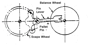
The detached pin lever escapement is shown below is a more sophisticated arrangement.
A hairspring coupled to the balance wheel keeps it oscillating. The balance wheel periodically pushes
the pin lever ( connecting the scape and balance wheels ) from one side to the other.
This push occurs when the balance wheel is passing through the point of maximum kinetic energy.
At this point the oscillator is best able to perform work without being distrubed.
After the balance wheel has moved the lever however the wheel is free to continue in motion.
It generally oscillates about 360 degrees. As a result, the balance wheel oscillator
is detached from all restraint during most of its cycle , so the timing accuracy is good.
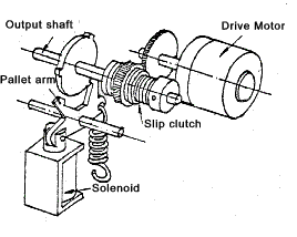
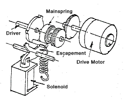
In many machine applications it is desirable to be able to vary the stepping rate. The adjustable rate escapement shown in below resembles the inverse escapement in ****. In the inverse device however the arm is the driver. In the unit shown an electric motor is driving a scape wheel through a slipping clutch. The scape wheel remains at rest until the solenoid is actuated. As one tooth on the pallet arm frees the scape wheel, the other pallet tooth moves to engage the wheel. As a result, the amount of motion is controlled and is independent of the length of the electrical pulse delivered to the solenoid. This mechanism is part of a heavy duty counter. An alternate method of loading the escapement is shown in fig 30. A motor winds a clock sspring from the centre . The outer end of the spring engages a drive pin on the scape wheel which is driven by the spring whenever the solenoid actuates the escapement.
The motor can be a normally stalled torque motor, continuously energised. Alternatively the motor can be turned on only when sensing switches indicate that the clock spring has run down (the switches sense the increase in spring dia as it unwinds.) Spring arrangements such as this are useful if the load requires short bursts of pulses, followed
by a long delay or dwell. The motor need not be large enough to accelerate the load
at the maximum pulse but only large enough to supply energy to the spring at an average pulse
rate. This can be quite low if the dwell time is a significant portion of the total cycle.
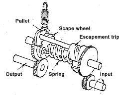
In another type of spring loaded escapement shown below input can be either continuous as shown or intermittent. Output is intermittent and occurs once per revolution of the input cam. In operation, the input winds a spring : continued rotation then releases the spring by triggering an escapement. This is called a "load of fire" escapement and isolates the input from sudden changes in load.M
The figure below shows another common machine escapement , input to the escape cam is continuous. The scape wheel is loaded by a stalled motor spring or slip clutch. the type of escapement is really just a holding ring-held plate combination & can be similar to the holding elements used with mutilated gears .
Impact shock and high acceleration are characteristic of any escapement since the load is released and stopped suddenly. Noise & wear can result. However the devices are frequently used whenever high indexing speed and /or precision are required. Linkage escapement Linkages are often used with other machine components to produce intermittent
motion. The example below is a typical application using a four bar linkage. Electronic escapements are used mostly in clocks and watches. They are electrically driven
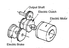
mechanical escapements and should not be confused with electronic timers. Clutch Brake Systems A clutch brake mechanism is often used to produce controllable intermittent motion; some manufacturers supply motors with built in clutch brakes. If the clutch and brake are themselves controlled by electrical signals as in the system shown below, the duration of drive and dwell can be easily varied. Power capacity and indexing speed depend of course on motor size and the capacity of the clutch and brake.
|
Links to Escapement Mechanism Design
|
|
Machine_Parts_Index
Mechanism general notes
