| |
Drawing Page Drawing Guide
|
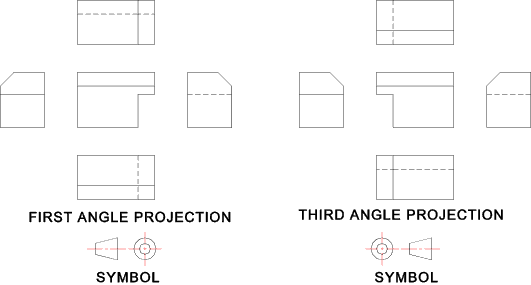
Projections First angle and third angle projection methods are acceptable.
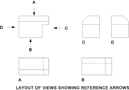
The symbol identifying the type of projection used should be placed in a space provided in the drawing block Views Using Reference Arrows.
The principal view on which all of the other views are based should be selected as being the most informative. This may be the view which is most recognisable during manufacture or use. i.e. the front view of a house or the side view of a car. Lines Used on Drawings..
FIGURE SHOWING LINETYPES
Two thicknesses of line should be used on a drawing. The "thick" line should be at least twice as thick as the "thin" line. The thickness of the line should be based on the sizes... 0,18mm 0,25mm 0,35mm 0,5mm 0,7mm 1,0mm 1.4mm and 2mm Line spacingThe minimum space between parallel lines should always be greater than twice the thickness of the heaviest line. Leader LinesLeader Lines terminate
Lettering Lettering should all be in capitals and underlining should be avoided.
The lettering size should be at least 3,5mm on the finished drawing/ plot(A0 ,A1). For larger
sized lettering such as the drawing number and title in the title block 5mm is used.
Details of the lettering is found on webpage Lettering . Smaller lettering sizes
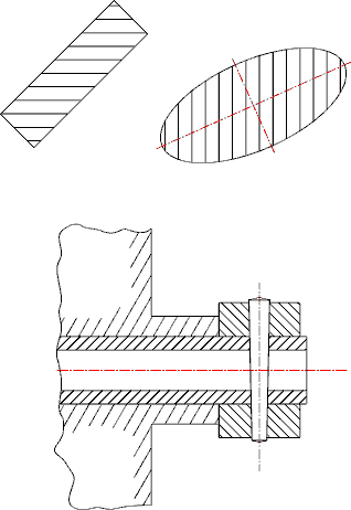
are acceptable on the smaller drawing sheet sizes A2, A3, A4 (2,5mm and 3,5mm respectively) Hatching Hatching is used to show areas of sections.
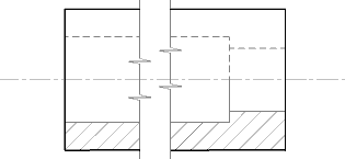
In case of large areas the hatching may be limited to a zone following the contour of the hatched area |
Useful Links On Drawing
|
|


