Brakes
Disk Brakes
|
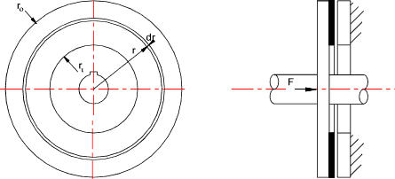
Introduction The Disk brake is based on a rotating ring (disk) which is mounted on the rotating shaft and a ring or pad of friction material which is forced against the rotating disk to retard its rotary motion. The force applied to the friction element may be manual, electrical, pneumatic, hydraulic or inertial via a mechanical linkage. Disk brakes are very useful for heavy duty applications because they can be arranged to dissipate heat rapidly and are equally effective in both rotation directions. Disk Brake Friction Materials A selection of disk brake materials with their important properties are provided on page Brake/Clutch materials Nomenclature
Theory There are two operating conditions applicable to disk brakes .
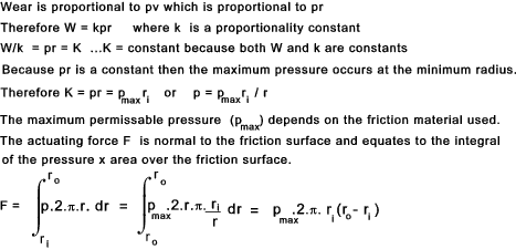
The wear (W)at any location on a brake is assumed to be proportional to the pressure intensity (p)and the associated relative velocity (v)of the local ring of contact.
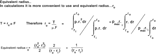
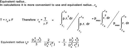
The torque capacity of a brake is the integral of the friction force (μ F) x Radius (r)
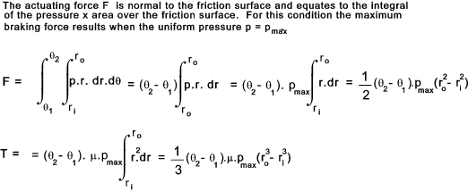
Uniform pressure When considering the capacity of a disk brake subject uniform pressure, every
point on the brake face is subject to the the maximum design pressure for the friction
material. This condition applies mainly to new brakes
The torque capacity of a brake is the integral of the friction force (μ F) x Radius (r)
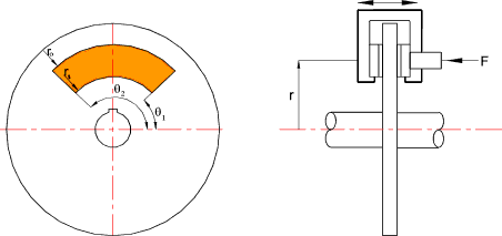
Disk Brake Pads, Caliper, Floating Caliper Disk Brakes These systems include an actuated caliper which is mounted on a fixed frame.
The braking effect results from brake pads which are attached to the inner faces of
the caliper being closed together the contact the rotating disk.
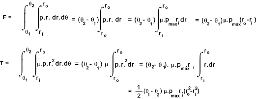
The wear at any location on a brake is assumed to be proportional to the pressure intensity (p)and the associated relative velocity (v)of the local contact.
Uniform Pressure
|
|
|
Brakes
