Drive_Index
Drive couplings
A coupling is used to connect two in-line shafts to allow one shaft (driver) to drive the second shaft(driven) at the same speed. A coupling can be rigid or, more normally, it can be flexible allowing relative radial, axial or angular movement of the two shafts. Unlike the clutch the coupling transmission is not designed to engage-disengage as a normal operation
Coupling Type
Note: Pictures of all the coupling types are to be found at the referenced links below i.e Renolds
| Coupling type | Description |
|
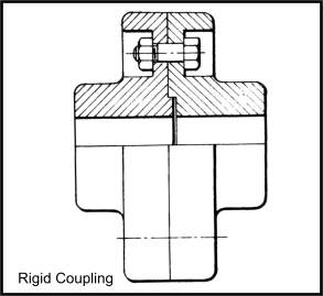
Rigid Coupling Flange locked onto each shaft. One flange with recess and the other with matching spigot. Flanges bolted together to form rigid coupling with no tolerance for relative radial, angular or axial movement of the shafts.
|
|
Muff Coupling Long cylindrical coupling bored and keyed to fit over both shafts. Split axially and clamped over both shafts with recessed bolts. Rigid coupling for transmitting high torques at high speeds |
|
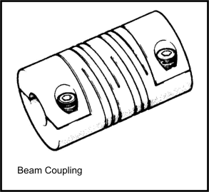
Beam Coupling Single piece cylindrical coupling with a hole bored through it entire length. Each end bored to suite the relevant shaft. The helical slot is machined in the coupling in the central region. The reduces the coupling stiffness. The coupling is positive with some flexibility. |
|
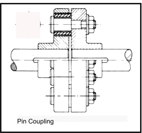
Pin Coupling As rigid coupling but with no recess and spigot and the Bolts replaced by pins with rubber bushes. Design allows certain flexibility. |
|
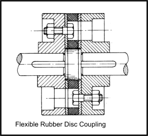
Flexible Rubber disc Couping As rigid coupling except that a thick rubber disc bonded between steel plates is located between the flanges. The plates are bolted to the adjacent coupling flanges. |
|
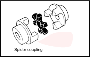
Spider Both half of the couplings have three shaped lugs . When the coupling halves are fitted together the lugs on one half fit inside the spaces between the lugs on the other side. A Rubber insert with six legs fits within the spaces between the lugs. The drive is by the lugs transmitting the torque through the rubber spider spacer... This coupling is only used for low power drives. |
|
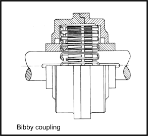
Bibby coupling The outer flanges of the two half couplings are serrated. A spring fits into the serrations connecting the two halves. |
|
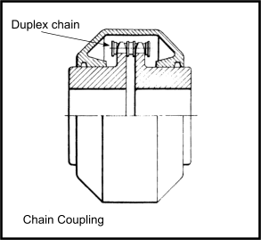
Chain Coupling Flanges replaced a sprocket on each shaft. The coupling is by a duplex chain wrapped over both adjacent coupling. |
|
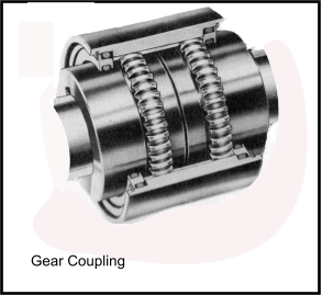
Gear Coupling Both coupling halves have a raised rim machined as an external gear. The sleeve which couples the two shafts comprises two halves bolted together, each half having a machine internal gear. This coupling requires lubrication. The coupling is capable of high speeds and high power capacity. |
|
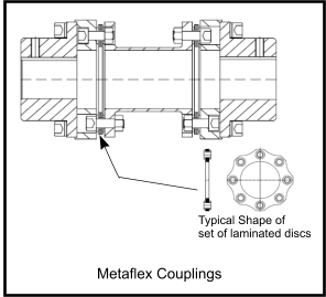
MetaFlex Coupling Coupling halves connected via stainless steel diaphragms (discs). High speed high torque capability with good dynamic balance. Single coupling will accommodate angular and radial misalignment and fitted in pairs also allows lateral misalignment. |
|
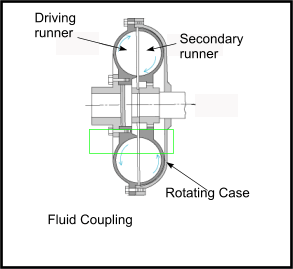
Fluid Coupling Based on both coupling halves having vanes within a housing (case) containing viscous fluid which rotates with the driving shaft. The rotation is transmitted from one side (Driving) to the other (Secondary) via the viscous fluid. The coupling provides a soft start. |
|
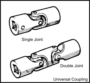
Universal Coupling Coupling which allows large angle between drive halves(20-30o). Generally based on a yoke mounted on each shaft . Between to yokes is mounted a trunnion cross. Needle bearings are used at the bearing points between the cross and the yokes. These type or units are used in pairs on carden shafts. Uses widely on rear wheel drive vehicle propshafts |
|
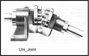
Universal Coupling- Simplest type of coupling which allows large angle between drive halves. Each side of coupling includes protruding pins. The halves of the coupling are fastened in a pivotting assembly. At all angles up to about 40o the pins interlock with each other and rotation on one half forces the other half to rotate. Low power use only . Not smooth. Not reliable. Really only suitable for remote manual operations. |
|
Drive_Index
