Brakes
Drum Brakes
|
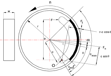
Introduction The drum brake widely is used on road vehicles and consists of a drum attached to the rotating wheel. The drum has an internal machined cylindrical surface. Inside the drum and protected from the environment are two shoes lined with friction material which can be pivotted to make a forced contact with the internal cylindrical surface. Nomenclature
Theory
The pressure distribution evaluation for the brake shoe assumes that the shoe
arm is rigid and the pressure is directly related to the distance from the pivot
point. The pressure is proportional to c sin θ or p = k sin θ
where k is some constant. k = p max /sin θ max... and... p = sin θ(p max /sin θ max) The torque capacity of a brake shoe is obtained by integrating the product of the
frictional force and the drum radius
The actuating force is calculated by taking moments about the brake shoe pivot point.
MFn is the moment due to the normal force between the shoe and the drum. MFf is the
moment due to the friction force.
The motion of the drum as shown result in an ACW friction moment and the normal reaction force of the drum also
results in an ACW moment as the two moments are the same self locking cannot occur. If the rotation is reversed
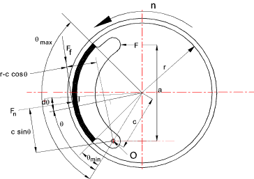
and the friction moment is CW then the resulting actuating force will be reduced and self-locking is possible. Opposite handed brake show The opposite handed brake shoe as shown below results in the friction moment being of opposite
to the normal force moment and the brake system is to some extent self energising with a possibility of self locking
|
Links to Brake Design
|
|
Brakes


