Introduction
Vee belt drives replaced flat belt drives for many applications because higher power
drives could be transmitted with more compact drive arrangements. With a
flat belt drive only one belt is used. With a vee belt drive a number
of belts are used. Flat belts and vee belts may, and do,slip as the loading
increases. For belt drives which drive without slip timing belts should
be used. Vee belts on higher power duties generally
have to be matched to ensure the drive power is shared.
For a flat belt drive the tangential friction force at the point of slipping is μR....
(μ= coefficient of static friction - R = radial force between the belt and the pulley ).
For a vee belt drive the equivalent friction force at the point of slipping
= μR /sin β.... (β is the vee half angle ) see below.
Therefore a vee drive has a maximum friction = (1/ sin β) x the flat belt friction.
e.g a for a vee belt drive with an internal angle of (2 .β) = 20o the maximum friction force
for a vee belt = 1/sin (10)= 5.75 x the maximum flat belt friction.
A a vee belt drive system, when correctly specified, can be expected to deliver
25000 hours of service (around 3 years continuous, or 5 years normal use) before belt
replacement is required.
Vee Belt Drives achieve drive efficiencies of about .
Practical Notes
- Setting the belt tension is readily achieved by jacking the pulleys apart and measuring the transverse distance the belt can move.
- Higher shaft torsional loads are handled by using multiple belt pulleys.
- A jockey pulley can be installed to increase the angle of contact and allow transfer of more power. It can be mounted on either the tight or loose belt side and adjusted inwards to provide more angle of contact.
|
Vee Belt Design
Vee belts are generally manufactured from a core of high tensile cord in a synthetic rubber matrix enclosed
in a fabric reinforce rubber lining.
The vee belt sections and the pulley groove dimensions are in accordance with British /European standards.
Relevant British Standard:
BS 3790:1995 ..Specification for endless wedge belt drives and endless V-belt drives
This standard refers to four belt sizes designated SPZ,SPA,SPB,and SPC.
The vee belt cross section are shown below.
| Section | Pitch Width | Nom Top width | Nom height |
Min. Dia | Mass/m** |
| mm | mm | mm | mm | kg/m |
| SPZ | 8,5 | 9,5 | 8,0 | 67 | 0,073 |
| SPA | 11,5 | 13,0 | 10,0 | 100 | 0,129 |
| SPB | 14 | 16,0 | 14,0 | 160 | 0,18-0.203 |
| SPC | 19 | 22,0 | 18,0 | 224 | 0,33-0,412 |
**The mass / m vary from different reference sources.
The pulley dimensions are based on the above standard are shown below:...
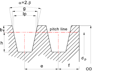
Belt
Section | lp
mm |
b
mm | h
mm | e
mm |
f
mm | α | g |
| SPZ | 8,5 | 2,5 | 9,0 | 12,0 | 8,0 | 34 (dp <80)
38 (dp > 80) | 10,0
10,2 |
| SPA | 11,0 | 3,3 | 11,0 | 15,0 | 10,0 | 34 (dp <118)
38 (dp > 118) | 13,1
13,5 |
| SPB | 14,0 | 4,2 | 14,0 | 19,0 | 12,5 | 34 (dp <190)
38 (dp > 190) | 16,6
16,9 |
| SPC | 19,0 | 5,7 | 19,0 | 25,5 | 17,0 | 34 (dp <315)
38 (dp > 315) | 22,5
22,9 |
Vee belt power capacity
The power transmission rating of a vee belt drive is based on the belts used, the number
of belts, the angle of wrap of the belt on the smallest pulley,and the rotational speed of the pulleys.
The rating required is selected as the product of the design load and an appropriate
service factor.
A formula for the number of belts (N) required for a duty power (Pd ) at
a service factor (K), using belts with a basic power per belt Pb, and
an angle of contact factor (F) and a belt length factor (E) for is provided below.
N = Pd. K / Pb.F.E
Angle of contact factor
The angle of contact ( θ) of the vee belt over the smallest pulley when
the pitch dia of the largest and smallest pulleys are (Dp & dp)
and the centre distance = C is provided below:
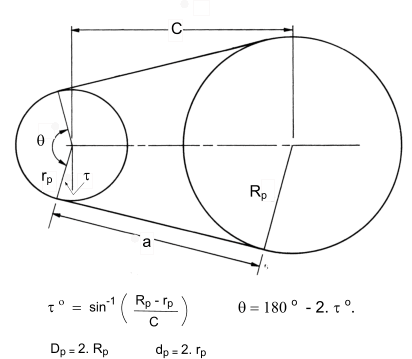
The angle of contact factor F varies from 1 for an angle of contact of θ of 180o down to
0,82 for and angle of contact θ of 120o.
Length factor
The pitch length of belt may be calculated (approximately)from the equation below
L = 2.C + p (D p + dp)/2 + (D p - dp)2 /4.C
or more accurately using
L = 2.C.cos A + p (D p + dp)/2 + (D p - dp).A
where A is in radians and sin A =(D p - dp)/2.C
The length factor reflects the effect of a belt pitch length other than a reference value.
For SPZ this reference length is 1592mm. The length factor various from 0,83 for a length 630mm up to 1.17 for a length of 3550mm
For SPA this reference length is 2278mm. The length factor various from 0,82 for a length 800mm up to 1.12 for a length of 4500mm
For SPB this reference length is 3204mm. The length factor various from 0,85 for a length 1260mm up to 1.15 for a length of 8000mm
For SPC this reference length is 5070mm. The length factor various from 0,86 for a length 2000mm up to 1.14 for a length of 12500mm
Typical power ratings
The power ratings below are based on the smaller pulley with 180o of belt wrap !!.
The ratings are based on a light duty application for a transmission working for less than
10 hours per day i.e a service factor K= 1. At the other extreme of a extra heavy duty drive e.g.direct on
line AC motor with frequent stops and starts, working for 24 hours /day a service factor K = 1,8
would be necessary. The basic power ratings shown below are used to establish the
drive power capacity of a belt drive system using a formula.
Belt
Section | Pulley Dia
mm | Power(kW) at motor speed |
| 2880(RPM) | 1440(RPM) | 960(RPM) |
| SPZ | 67 | 1,75 | 1,05 | 0,77 |
| 140 | 6,97 | 4,02 | 2,84 |
| SPA | 100 | 4,12 | 2,61 | 1,92 |
| 200 | 15,1 | 9,4 | 6,72 |
| SPB | 160 | 12,1 | 7,85 | 5,73 |
| 400 | 25,7 | 29,8 | 22,0 |
| SPC | 224 | 18,5 | 16,6 | 12,7 |
| 560 | - | 62,7 | 53,3 |
Service Factors
When designing belt drives it is normal to apply a service factor to the drive operating
load to compensate for allow for different driver type, driven load types and operating
periods. Typical service factor values are included on the linked page Service Factors
Basic Theory
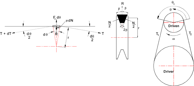
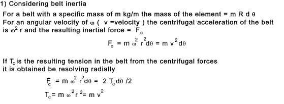
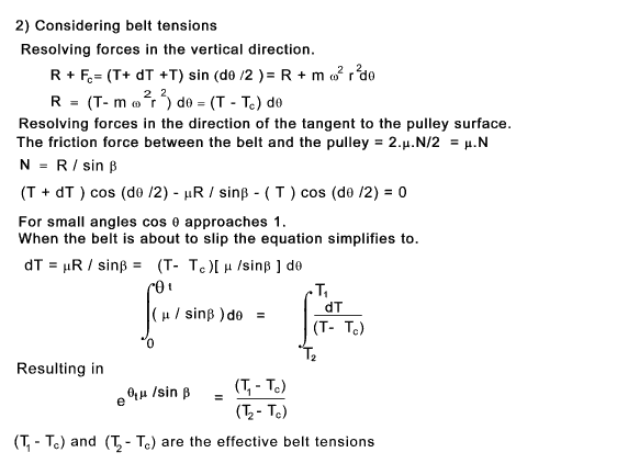
Fc = Centrifugal Force (N)
R = Pulley reaction Force (N)
P = Max power transferred kW
T = Belt tension
Tc = Belt tension due to centrifugal force
μ = Coefficient of friction.
f = Effective coefficient of friction = μ/sin β
b = Belt width (m)
ω = Angular velocity of pulley (rad/s)
n = Rotational Speed (RPM)
θ = Angle of belt lap
2.β = Internal Angle of Vee
v = Linear velocity of belt (m/s)
|
Notes:
If two pulleys of different diameters are used then in driving to the limit
the belt will slip on the smaller pulley first
For vee belt drives an effective coefficient of friction f = μ/sin β is used and
an approximate practical value for this is 0,512
Power transferred by a vee belt
The power transferred =
P = (T1 - T2 ).v / 1000
= (T1 - Tc) - (T2 - T c ).v / 1000
= (T1 - T2 ) (1 - e- θμ/sin β ).v /1000
= (T1 - T2 ) (1 - e- θf ).v /1000
|


