| |
Fatigue Index Impact Loading
|
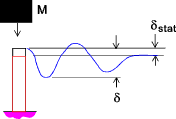
Introduction Generally when the strength of machine elements are considered it is assumed that the loading is static or applied gradually. This loading condition is often not the case, the loading may be cyclic requiring assessment for fatigue. Fatigue or it may involve impact or suddenly applied loads. When loads are applied suddenly and when the loads are applied as impact loads the resulting transient stresses (and deformations) induced in the machine elements are much higher than if the loads are applied gradually. This effect is shown in the diagram below
It is normal practice to design machines such that impact loads are eliminated or reduced by
inclusion of shock absorbers. Inclusion of low cost, mass produced, shock absorbers
can virtually eliminate the increased stresses and deformations resulting from impact loads. Notation
Linear Impact deflections and stresses (gravity loads) Important note: The notes below represent a very simple view of the loading condition and
do not consider more real case involving shock waves being propagated through the loaded member or
the moving mass
In accordance with conservation of energy the potential energy of the weight is converted to elastic strain energy.
This may be expressed as a quadratic equation
This is solved for the maximum deflection δmax as follows
The weight applied gradually would result in a deflection δst thus
Note:
This can be expressed as
The resultant maximum force is simply Pmax = k δmax and the resultant maximum stress = σmax = Pmax/ A This may be expressed as
For the calculation of the stress due to a suddenly applied load with h = 0 σmax = 2 σst Linear impact deflections and stresses (kinetic impacts ) Important note: The notes below represent a very simple view of the loading condition and
do not consider more real case involving shock waves being propagated through the loaded member or
the moving mass
The resulting equation is
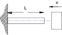
The resultant maximum deflection equals..
Noting that the static deflection = Wl/AE this equation can be written
The equivalent maximum stress =
Noting that the static deflection = Wl/AE this equation can be written
Beams
Using similar principles as expressed above it can be easily proved using principles of conservation of energy that.
and
If the impact is horizontal instead of vertical . The resulting deformation and stress resulting from the impact are
Note: The above approximate relationships can been applied generally to most structural systems subject to distortion with the elastic range when subject to impact loading Energy losses on impact The above equations are very approximate and include many assumptions. A very important
assumption is that all of the energy ( based on h or v2) is used up in producing the same distortion
as would result from static loading. In reality, some kinetic energy is lost in internal friction. Account can
be taken for these losses by multiplying h or v2 by an appropriate factor K. This factor is derived from
the Mass of the moving body (M) and the mass of the beam or bar (M1). The factor is different for different
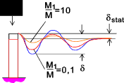
loading systems ass follows. if M1/M is say 0,1 then K = 0,95.. This is illustrated in the figure below
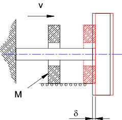
1) A moving mass M striking axially one end of a bar of mass M1. The other end of the bar being fixed...
2) A moving mass M striking traversely the end of a beam of mass M1...
3) A moving mass M striking traversely the center of a beam with simple supported ends of mass M1....
4) A moving mass M striking traversely the center of a beam with fixed ends of mass M1. ..
Impact stresses considering propagation of shock waves- Unsupported bar
When a impact force is suddenly applied to and elastic body , a wave of stress is propogated traveling through the body with a velocity..
w = weight /unit volume (kg/m2), v = velocity (m/s)
If the mass of the moving body is very large compared to the mass of the bar the wave of compression bounces back from the far end of the bar as a wave of tension and returns to the struck end after a time period . t p = 2L / V If the mass of the moving body is very large compared to the bar so that it can be
considered infinite then after breaking contact the moving bar will move away from the
impacting mass with a velocity of vb= 2v. The moving bar will be stress free.
The moving bar is left vibrating with a stress intensity of
Impacts considering propagation of shock waves- bar with one end supported
For the case of a bar with one end fixed , the wave of compressive stress resulting from the impact on the unsupported end is reflected back unchanged from the supported (fixed end) and combines with the advancing waves to produce a maximum stress approximately equal to..
|
Links to Machine Loading
|
|
Fatigue Index


