|
Introduction
The notes below are outline notes based on information obtained from a variety of sources. I have listed the relevant european
standards. The notes on this page have not yet been checked against the standards. It is recommended that for final detail design,
reference is made to the standards.
Relevant Standards
BS EN 894-1:1997 :Safety of machinery. Ergonomics requirements for the design of displays and control actuators. General principles for human interactions with displays and control actuators
BS EN 894-2:1997: Safety of machinery. Ergonomics requirements for the design of displays and control actuators. Displays
BS EN 894-3:2000: Safety of machinery. Ergonomics requirements for the design of displays and control actuators. Control actuators
BS EN 894-4:2010: Safety of machinery. Ergonomics requirements for design of displays and control actuators. Location and arrangement of displays and control actuators
Size of lettering and Symbols
Below are list suggested for sizes of letter and symbols to be used on controls and machines
used in well illuminated areas..
Black letters against white background are clearer to read in normal daylight
conditions. In relatively dark conditions white letters on a dark background are better.
| Distance from Eye (mm) | Height of Letters or Figures (mm) |
| Less than 500 | 2.5 |
| 501 to 900 | 5.0 |
| 901 - 1800 | 9.0 |
| 1801- 3600 | 18.0 |
| 3601 - 6000 | 30.0 |
Control Directions
Rotary Controls.. The accepted direction for rotary controls is Clockwise motion of control
to increase the variable. Anti-clockwise motion to decrease the variable...
In direction controls Anti-clockwise motion results in a turn to the left in forward motion
and clockwise motion result in turning to the right in forward motion..
Lever controls.. The accepted direction for linear controls is movement forward,to right or up to increase
variable and movement towards you, to left or down to reduce variable...
Relationship Between Controls & Displays
Push Buttons..
A push button can be arranged for operation by finger or by hand..
Suggested dimensions..
| Diameter..(finger operation) | 12 -15 mm |
| Diameter..(emergency stop ) | 30 -40 mm |
| Travel....(finger operation) | 03 -10 mm |
| Resistance.to motion.(finger) | 2.5 - 5.0 N |
| Diameter...(hand operation) | 60mm |
| Travel...(hand operation) | 10mm |
| Resistance.to motion.(hand) | 10 N |
Toggle Switches
Toggle switches should only have two positions "on" and "off" they should preferably
be located on vertical panels with vertical toggle motion.
The angle of motion should be about 45o
Diameter.. 3 - 25mm
The length..12- 50mm
Resistance to movement..2.5 - 15N
Levers
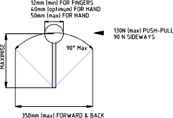
Large levers are sometimes used where significant operating forces are required.
Maximum forward and back motion 90ototal.
Maximum forward and back motion 350mm total.
Maximum lateral motion 45o total.
Maximum lateral motion 150mm total.
Maximum operating force 130N forward and back.
Maximum operating force 90N sideways.
Rotating Knobs
Rotating knobs provide a convenient method of controlling variables. They should
conveniently fit the hand , be easy to rotate, and should not impair viewing.
Two options are available knobs 1) Rotating Switches with indented motion (click stops)
and 2) continuous motion knobs.
Rotating Switches.
Successive positions should not be less than 15o apart if the knobs are controlled
by a pointer in view.
Successive positions should not be less than 30o apart if the knobs are controlled
by a feel.
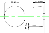
Suggested Design Parameter.
| Diameter.. | 35 -75 mm |
| Height | 20-50mm |
| Continuous resistance | 0.15Nm |
| Maximum torque) | 320 Nm |
| Resistance (at clicks)... | 12-18N |
| Angle for each step... | 15o to 40o |
Continuous Motion Knobs
Continuous motion knobs allow precise regulation and allow control using finger or
hand grip i.e delicate movement or rough movement..
Suggested design parameters
| Diameter..(finger operation) | 10 -30 mm |
| Diameter..(whole hand ) | 35 -75 mm |
| Height....(finger operation) | 15 - 25 mm |
| Height ...(Hand Control) | 30 - 50 mm |
| Diameter...(hand operation) | 60mm |
| Max turning torque...(small knobs) | 0.8Nm |
| Max turning torque...(large knobs) | 3.2Nm |
Pointed Bar Knobs
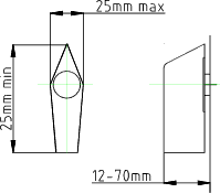
Arrow shaped , pointed bar knobs allow settings to be made quickly and
conveniently...
Suggested design parameters
| Length.. | 25mm min. |
| Thickness | 25 mm max. |
| Height.. | 12 - 70 mm |
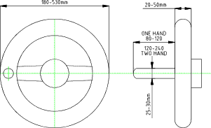
Handwheels
Handwheels allow large forces to be applied because two hands can be used and gearing
can be included for slow movement.
Suggested design parameters
| Diameter | 180- 530mm |
| Dia of rim | 20 to 50mm |
| No of Spokes | Minimise |
| Resistance (min) | 20N |
| Resistance (max) Single Handed | 135N |
| Resistance (max) Two Handed | 225N |
Cranked Handwheel
Rotating cranked wheels allow for operating of machines over long movements using
continuous rotation of the crank. The gearing between the crank and the
motion may be fine
or coarse and may be switched between ratios. A crank handle allows
fast motion and the handwheel can be used for more precise motion.
Suggested design parameters
| Radius of crank for low toque ( up to 200 RPM) | 60 - 120mm |
| Radius of crank for high toque ( up to 160 RPM) | 150 - 220mm |
| Radius of crank for quick setting | up to 120mm |
| Resistance Torque (120mm rad. Crank) | 0.5 to 2.5 Nm |
| Resistance Torque (240mm rad. Crank) | 3.0- 4.0 Nm |
| Handle diameter | 25-30mm |
| Handle Length (one handed) | 80 to 120mm |
| Handle Length (two handed) | 190 to 250mm |
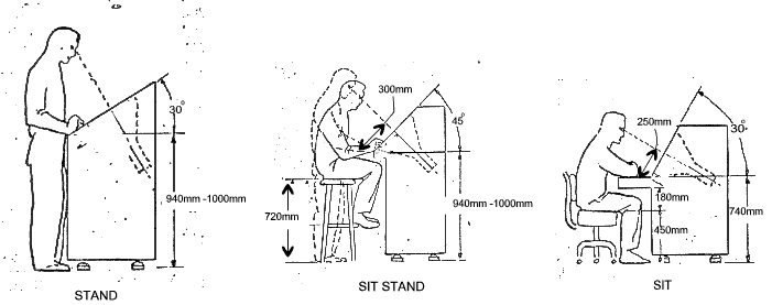
Angular Mounting of Monitors
These sketches are very dated and should only be used for general guidance
| 