Introduction
This page includes notes reviewing the principles determining the properties
of engineering materials. The notes will progress quickly from the atoms to grains
and will try to describe how engineering materials acquire the properties which
make them useful...
Atoms:Description ....Additional notes on atoms
n conventional theory all matter is made of atoms
An atom is a nucleus comprising protons and neutrons and surrounding shells of electrons.. Hydrogen has one proton and no neutrons
The proton is a positive charged particle an electron is a negatively charged particle and a neutron has no charge
The neutron has a similar mass to the proton and electron mass = 1/1836 x the mass of the proton
The element atomic number is the number of protons in the nucleus of an atom and defines its chemical properties
The mass number of an atom is the total number of protons + neutrons in an atom.
The relative atomic mass of an element is the mass measured in comparison with carbon-12 which has a Relative Atomic mass of 12
A neutral atom has an equal number of protons and electrons
The chemical properties of an atom are not affected by the number of neutrons.
Elements of atoms with the same atomic number but different number of neutrons are called isotopes
There are about 115 different elements of which 92 occur naturally
Atoms:Electronic Structure
The electrons of an atom are arranged into a number of shells depending on the Atomic number
Hydrogen has only one Shell (K shell). Uranium has a full quota of shells (K,L,M,O,P and Q)
These shells have associated Quantum numbers (K = 1, L = 2, M = 3, N = 4, O = 5, P = 6, Q = 7)
Within the shells electrons can have certain energy levels ( s, p d, f, g h ).
These energy levels have associated Azimuthal quantum numbers s = 0, p = 1, d= 2, d = 3, g = 4, h = 5.
The ability of an element to form compounds is directly related to the population of electrons in these shells
The shorthand notation for iron ( Fe = 1s 22s 2 2p 63s 23p 63d 64s 2 )
Within each shell of an atom the maximum number of electrons at each azimuthal level is as follows;
| Shell | s | p | d | f | g | h |
| K | 2 | | | | | |
| L | 2 | 6 | | | | |
| M | 2 | 6 | 10 | | | |
| N | 2 | 6 | 10 | 14 | | |
| O | 2 | 6 | 10 | 14 | 18 | |
| P | 2 | 6 | 10 | 14 | 18 | 22 |
The sketch below illustrates the directional nature of the s and p electrons based on the
principle of wave mechanics and identifies regions in which electrons are very likely to occur. At the most 2 electrons
can be present in any orbital

Element
An element is is a pure substance which cannot be split by chemical means into other substances
Periodic Table Periodic Table
The atoms have been arranged in a table called the Periodic Table.
In this table the atoms have been arranged in vertical columns based on the similar
chemical properties due to their electron configuration
Molecule
Elements can combine physically in fixed proportions to form molecules of compounds
Compounds are entirely different to the constituent elements with their own chemical and physical properties
Many simple molecules are made up from only one type of atom H2, I2
There are two principle types of molecules organic and inorganic.
Organic molecules are based on Carbon, Oxygen, Nitrogen and Hydrogen.
Molecules associated with living matter, oil etc are organic.
Inorganic molecules include minerals, ceramics etc.
Valency
The valence of an atom is related to the ability of the atom to enter into chemical
combination with other elements and is most often determined by the number of electrons
in the outermost combined s,p level.
The atomic stability of atoms relates to the valency- If an atom has a valency of zero (He, Ne,
Ar, Kr, Xe, Rn) there are no electrons or electron voids in the outer shell to create
a chemical bond and the element is inert. Argon has an electronic structure
1s22s22p63s23p6
The M shell has its full complement of 8 electrons(3s23p6 )..
On the opposite end of the valency scale are those elements
with a valency of seven (F, Cl, Br,I, At) as an example Chlorine (Cl) with an electronic structure
1s22s22p63s23p5 contains seven electron in its
outer M shell ( 3s23p5 ). This is very reactive because it has a strong tendency to
fill its outer shell with an electron - It is electronegative..
Molecular Bonds
Covalent Bond
Covalent bond occur when two atoms share a pair of outer electrons (Valence electorns). This type of bond is hard to
make but when made is rigid and strong. This type of bond occurs in organic compounds and sometimes ceramics.
The ideal covalent bond where the valence electrons are shared equally is between identical atoms. The silicon atom has 4 electrons in
its outer shell. It fills its outer shell by forming a covalent bond with four surrounding atoms each contributing 1 electron.This is a very strong
bond but it is directional.
For material with a covalent bond to distort the bond must be broken it cannot easily
re-orientate itself. Materials with covalent bonds are often brittle and are poor conductors.
Ionic Bond
The bond between two different atoms when one atom (the cation) donates its valence electrons to another
atom (the anion). The resulting electrostatic charge bonds the two atoms together
Metallic Bond
The electrostatic charge between the positively charge cores of the atoms and the collective
valence atoms. The metallic elements have a low valence, easily give up their valence electrons to
form a "sea" of electrons surrounding the atoms. The valence electrons are free to move
and form a negatively charged soup. The positively charged atom cores are held within
the electron soup by their charge, thus producing the metallic bond.
The metallic bond
allows electrons to move freely in the electron soup under the effect of external electrical potential difference.
Thus metallic bond thus allows metals to be good conductors.
The metallic bond has no directional preference..
Van der Waals Bond
These are weak electrostatic bonds between molecules or groups of atoms. They can often be
broken when the material changes state i.e. heating water to its boiling point breaks the
weak Van der Waals and converts the water to steam. The primary covalent bond however is
not affected and the water molecule remains in tact.
Binding Energy
The atoms arrange themselves within a bonding regime such that they are at a minimum
energy level. This is when there is a balance between the attractive and
the repulsive forces. The spacing at this low energy level equilibrium distance is called the
Interatomic spacing
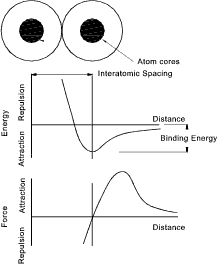
Binding energy levels for different bonding regimes are listed below
Strong Primary Bonds
- Ionic Bond ..625 to 1550 kJ/mol
- Covalent Bond ..520 to 1200 kJ /mol
- Metallic Bond..100 to 800 kJ /mol
Weaker Secondary Bonds
- Van der Waals ..0,02 to 40 kJ/mol
- Hydrogen Bond ..10 to 40 kJ /mol
- Dipole-dipole ..0 to 20 kJ /mol
|
The Modulus of elasticity is related to the slope of the force distance curve
Atomic Arrangements
In matter atoms arrange themselves in a variety of ways. Depending on the conditions
and the properties of the matter. A number of the possible atom arrangements are listed below;
- No order with large spaces between the atoms relative to the atom cross section - This occurs in gases
- Short range order- Water has a short range order in that each molecule consists of one Oxygen and
two Hydrogen atoms bound with covalent bonds. These molecules have only
loose ties with other water molecules. Glass materials most often are arranged
in short range order i.e. he molecules are generally spaced throughout the material in a no order i.e. and amorphous arrangement.
- Long range order - Metals, semiconductors and some ceramics and polymers arrange themselves in long range
order. The atoms form into gridlike lattice structures through the entire material. These materials can form
into large crystals based on the natural geometry of the lattice
|
The arrangements of the atoms has a significant affect on the property of the material..
The diagram below indicates the more important crystalline lattice arrangements of atoms. This diagram is a diagrammatic representation. In
fact when multitudes of atoms are in crystals together the cubic or hexagonal arrangement will
not be apparent.
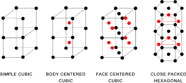
The diagram below indicates the simple dimensions used to dimension different types of
lattice structure. A simple cubic structure requires only one dimension "a".
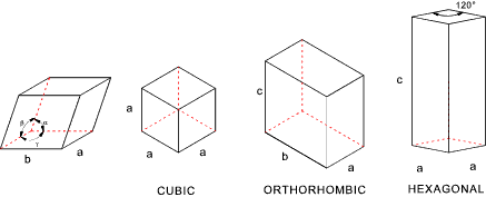
Certain parameters can be easily allocated to the lattice structures.
Lattice Points
- The SC lattice has 8 lattice points each shared by 8 cubes there are thus 1 lattice points per cube
- The BCC lattice has 9 lattice points,8 are shared each by 8 cubes and one is not shared: there are thus 2 lattice points per cube
- The FCC lattice has 14 lattice points,8 are shared each by 8 cubes: 6 are shared each by 2 cubes: there are thus 4 lattice points per cube
|
Packing Factor. This is the fraction of the space occupied by the atoms assuming each atom is
a solid sphere..
| The radius of an atom is r & there are 4 atoms per cube |
| The volume of an atom is (( 4 p r 3 / 3 ) |
| The volume of the unit cell is a3 |
| It can easily be proved that for a FCC a = 4.r / √2 |
| Therefore the packing factor = (4)( (4/3) pr3 / (4 r / √2 )3)= 0,74 |
Table of Atomic Radius
Note: 1 angstrom (�) - 10-10m
| Metal | Atomic Radius |
| Angstron Units |
| Aluminium | 1,431 |
| Cadmium | 1,490 |
| Chromium | 1,249 |
| Cobalt | 1,253 |
| Copper | 1,278 |
| Gold | 1,442 |
| Iron | 1,241 |
| Lead | 1,750 |
| Molybdenum | 1,263 |
| Nickel | 1,246 |
| Platinum | 1,387 |
| Silver | 1,445 |
| Titanium | 1,445 |
| Tungsten | 1,371 |
Coordination number..The number of atoms adjacent to any particular atom i.e the number of neighbours is termed
the coordination number. In crystalline lattice structures the coordination number is one indication
of how tightly the atoms are packed together. The simple cubic has a coordination number = 6, the Body Centred Cubic (BCC)
has a coordination number = 8 and the Face centred cubic (FCC) has the theoretical maximum coordination number = 12..
Characteristics of common metallic crystals
| STRUCTURE | a vs r | Atoms/Cell | Coordination
Number | Packing Factor | Metals |
| Simple Cubic(SC) | a = 2r | 1 | 6 | 0,32 | None |
| Body Centered Cubic(BCC) | a = 4r /√3 | 2 | 8 | 0,68 | Fe, Ti, W,Mo,Nb,Ta,K,Na,V,Cr,Zr |
| Face Centered Cubic(FCC) | a = 4r /√2 | 4 | 12 | 0,74 | Fe, Cu, Al,Au,Ag,Pb,Ni,Pt |
| Hex Close Packed(HCP) | a = 2r
c= 1,633a | 2 | 12 | 0,74 | Ti, Mg, Zn,Be,Co,Zr,Cd |
Calculation of Density of Iron (BCC) based of lattice parameters
he atomic radius of iron = 1,24 Angstrom units.
For a BCC structure the lattice characteristic value a = 4r / √3 . a= 2.864
The atomic mass of iron is 55,85 a.m.u (see table below)
The number of atoms per cell = 2.
Avogadros number = 6,02 x 10 26 atoms / kg mole
For Iron with a BCC structure a = 2,864 Angston units = 2,864 x 10 -10m
The density of iron = (2).(55,85) / [(2,864x 10 -10m )3.6,02 x 10 26 ]
= 111.70 /141,422 .10 -4 = 7898 kg/m 3
Planes in the unit cell
Certain planes of atoms in a crystal are important in considering the mechanical properties
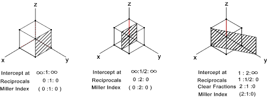
of the material e.g. metals deform along planes that are most tightly packed. Miller indices
are used to identify planes in unit cells of the crystals.
The simple rules for designating the planes are as follows
- If the plane passes through the origin select a new origin
- Identify the points, in terms of the cell side "a", that the plane intersects the x ,y,z axes
- Take the reciprocal of the intercepts
- Clear fractions but do not reduce to lowest integers
- Enclose resulting numbers in brackets ( a,a,a ). Negative numbers should have a bar over the number
|
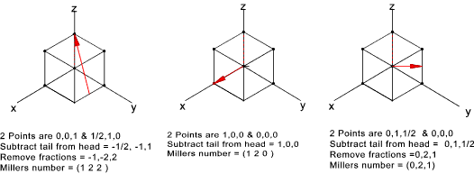
Directions in the unit cell
s for planes, important direction have to be identified in a crystal ..
The simple rules for designating the directions in the unit crystal are as follows
- In the Right Hand Coordinate system determine the coordinates of 2 point in the considered direction
- Subtract the coordinates of the tail point from the head point
- Take the reciprocal of the intercepts
- Clear fractions or reduce to lowest integers
- Enclose resulting numbers in brackets ( a,a,a ). Negative numbers should have a bar over the number
|
Anisotropy due to Atomic arrangement of crystals
The atoms are arranged with different packing densities in different directions, the mechanical
properties also vary. Crystalline materials are therefore fundemenatally anisotropic.
This is not apparent in manufactured metal products because the crystal are arranged in grains which are
themselves randomly orientated. Below is a table showing the variation modulus of elasticity of metals
in crystal in different directions.>
Young's Modulus (E) in GPa
| Material | [100] | [111] | Random |
| Al | 64 | 77 | 70 |
| Cu | 68 | 195 | 127 |
| Fe | 134 | 283 | 210 |
Interstitial Atoms
In any crystal structure there are small voids between the atoms called interstitial sites.
These sites can be partly filled with small atoms of other elements. These atoms may be impurity
atoms or they can be atoms included deliberately to create metal alloys. Steel is created as a result
of carbon atoms in the interstitial sites.
The interstitial atoms have coordination numbers which relate to the main crystalline
structure and the relative size of the atoms..An interstitial atom can be a close fit
in the interstice, it can be a tight fit resulting in tension in the main crystal bonds,
and it can be a loose fit which is not allowed and the interstitial atom will tend to move to a tighter space.
Strength of Metals
The theoretical strength of a pure metal in a crystalline arrangement in far higher than the
strength experienced in real life. For example the theoretical tensile strength of iron is
about 10 GPa ( 10^4 N/mm2 ). In reality pure iron has a tensile strength at yield
of about 20 MPa (20 N/mm2 ). This discrepancy occurs in all engineering materials.
Premature failure occurs by a number of mechanisms the two most important being brittle failure
as a result of high localised stresses at surface crack locations, and ductile failures resulting from
dislocations moving along slip planes
.
It has been possible to produce on a laboratory scale very fine threads of materials which have no surface cracks and have
virtually no internal imperfections which have strengths approaching of the theoretical
strength of substance under test.
Dislocations
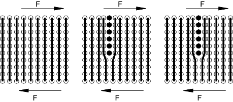
In a normal crystal arrangement the atoms are in fixed repeated locations relative to
each other and high stresses are required to break the numerous bonds and cause the
atoms to move from one crystal position to another. However in nature, dislocations
occur where a plane of atoms are inserted to distort the lattice structure as shown (simplified in 2D)
below. The result of this effect is that under relatively low shear stresses the
dislocation moves along in the direction of the imposed stress.
Edge Dislocation
The edge dislocation is the simplest type of dislocation. This dislocation,
in theory destroys itself when the dislocation plane arrives at the crystal boundary.
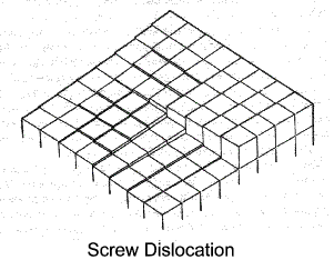
Screw Dislocation
The screw dislocation shown diagrammatically below is a type which is, to some extent, self
propagating - it does not destroy itself at a crystal boundary..
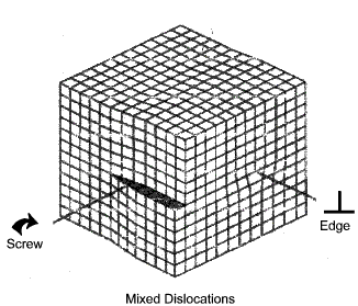
Mixed Dislocation
A mixed dislocation is a combination of the above two dislocation types. In practice
the vast majority of dislocation systems are mixed vectors
Controlling dislocations
Dislocations occur naturally and they increase in number as a result of stress and strain.
The slip occurring as a result of dislocations is along defined directions called slip planes and is
a shear phenomena. Ductile metals are ductile because of the action of dislocations.
It is clear that the strength of a ductile metal is improved if the free movement of dislocations can
be restricted. There are a number of methods of restricting the movement of dislocations as listed below
- Straining and distorting the crystal structure by introducing interstitial, substitutional atoms ..Alloying
- Reducing the size of crystals by generating smaller grains...Hardening, Heat treatment
- Increasing the number of dislocations such that they interfere with each other ...Work hardening
|
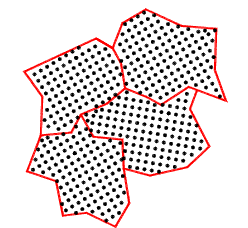
Grains
The microstructure of metals and many other solids consists of grains. A molten metal is
poured into a sand mold and allowed to air cool slowly will result in the production of coarse grains.
Pouring a molten metal into a metal mold with enhanced cooling produces finer grains. Introducing forced
circulation of water /oil in the metal mold produces even finer grain structures (Die casting.
Within each grain the structure is considered to be entirely crystalline in natures. Grain surfaces are highly
stressed regions because the crystalline structures are interrupted and the local atoms
interatomic distances are compressed or stretched. It is clear that if the average grain
size is increased then the strength of the material is reduced. The energy associated with
the surface area is reduced and the dislocation paths are reduced. A significant proportion
of the heat treatment processes related to the refining of the grains to developed increased strength
and control the ductility.
Brittle Fracture
Brittle fracture occurs with virtually no plastic flow or reduction in area. Separation takes
place along cleavage planes and appears as bright granular surfaces. Brittle fracture will show
the fracture planes to be generally perpendicular to the acting tensile force. The normal stress
on the plane of fracture will be higher than the stress on any other plane
All solid materials distort due to external forces. Internal stresses are created, as a result of the stretching or
compressing of atomic bonds. These stresses balance and support the external forces.
Real materials include a number of microscopic/ macroscopic cracks.
In materals under stress the depth /sharpness of these cracks result in regions of high
stress concentrations. Ductile materials included mechanisms to
reduce/ disperse the local stresses (dislocations ) and therefore the high localised
stresses are not catastrophic.
In brittle materials the the stress concentrations which can be over 100 times
the average stress cause the crack depths to increase. The increased crack depth results
in an increase of the stress concentration. This leads to progressive crack growth leading
to possible failure unless.
Thus a brittle fracture results from two important factors : the presence of cracks and the
absence of a mechanism for dispersing the high localised stresses.
A number of common materials (glass, carbon etc.) made with a surfaces having
no microscopic cracks has proved immensely strong. Carbon steels which have been
heat treated such that the grain size is so small that dislocation movement is very limited
is relatively brittle compared to the same steel which has been annealed to increase the grain size
|


