Introduction
Linkages include garage door mechanisms, car wiper mechanisms, gear shift mechanisms. They are a very
important part of mechanical engineering which is given very little attention...
A link is defined as a rigid body having two or more pairing elements which connect
it to other bodies for the purpose of transmitting force or motion . In
every machine, at least one link either occupies a fixed position relative to the
earth or carries the machine as a whole along with it during motion.
This link is the frame of the machine and is called the fixed link.
An arrangement based on components connected by rotary or sliding interfaces only is called a linkage.
These type of connections, revolute and prismatic, are called lower pairs. Higher pairs are based on point line or curve
interfaces. Examples of lower pairs include hinges rotary bearings, slideways , universal couplings. Examples of higher pairs
include cams and gears.
Kinematic analysis, a particular given mechanism is investigated based on the
mechanism geometry plus factors which identify the motion such as input angular
velocity, angular acceleration, etc. Kinematic synthesis is the
process of designing a mechanism to accomplish a desired task.
Here, both choosing the types as well as the dimensions of the new mechanism can be
part of kinematic synthesis.
Examples of Lower Pair Links with associated Degrees of Freedom
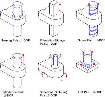
Planar, Spatial and Spherical Mechanisms
A planar mechanism is one in which all particles describe plane curves is space and all
of the planes are co-planar.. The majority of linkages and mechanisms are designed as planer systems. The main
reason for this is that planar systems are more convenient to engineer. Spatial mechanisms are far
more complicated to engineer requiring computer synthesis. Planar mechanisms ultilising only lower
pairs are called planar linkages. Planar linkages only involve the use of revolute and prismatic
pairs
A spatial mechanism has no restrictions on the relative movement of the particles. Planar and spherical mechanisms
are sub-sets of spatial mechanisms..Spatial mechanisms / linkages are not considered on this page
Spherical mechanisms has one point on each linkage which is stationary and the stationary point of all the links
is at the same location. The motions of all of the particles in the mechanism are concentric and can be repesented
by their shadow on a spherical surface which is centered on the common location..Spherical mechanisms /linkages are not considered on this page
Mobility
An important factor is considering a linkage is the mobility expressed as the number of degrees
of freedom. The mobility of a linkage is the number of input parameters which must be controlled
independently in order to bring the device to a set position. It is possible to determine
this from the number of links and the number and types of joints which connect the links...
A free planar link generally has 3 degrees of freedom (x , y, θ ).
One link is always fixed so before any joints are attached the number of degrees of freedom of a linkage assembly with
n links =
DOF = 3 (n-1)
Connecting two links using a joint which has only one degree of freedom adds two constraints. Connecting
two links with a joint which has two degrees of freedom include 1 restraint to the systems.
The number of 1 DOF joints = say j 1 and the number of joints with 2 DOF's
= say j 2.. The Mobility of a system is therefore expressed as
mobility = m = 3 (n-1) - 2 j 1 - j 2
Examples linkages showing the mobility are shown below..

A system with a mobility of 0 is a structure. A system with a mobility of 1 can be fixed
in position by positioning only one link. A system with a mobility of 2 requires two links to be positioned to
fix the linkage position.
This rule is general in nature and there are exceptions but it can provide a very useful initial
guide as the the mobility of an arrangement of links...
Grashof's Law
When designing a linkage where the input linkage is continuously rotated e.g. driven by
a motor it is important that the input link can freely rotate through complete revolutions.
The arrangement would not work if the linkage locks at any point.
For the four bar linkage Grashof's law provides a simple test for this condition
Grashof's law is as follows:
| For a planar four bar linkage, the sum of the shortest and longest links cannot be greater
than the sum of the remaining links if there is to be continuous relative rotation between two members. |
Referring to the 4 inversions of a four bar linkage shown below ..Grashof's law states that one of the links (generally the shortest link) will be able to
rotate continuously if the following condition is met...
b (shortest link ) + c(longest link) < a + d
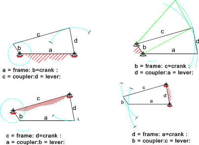
Four Inversions of a typical Four Bar Linkage
Note: If the above condition was not met then only rocking motion would be possible
for any link..
Mechanical Advantage of 4 bar linkage
The mechanical advantage of a linkage is the ratio of the output torque exerted
by the driven link to the required input torque at the driver link.
It can be proved that the mechanical advantage is directly proportional to
Sin( β ) the angle between the coupler link(c) and the
driven link(d), and is inversely proportional to sin( α )
the angle between the driver link (b)
and the coupler (c) . These angles are not constant so it is clear that the
mechanical advantage is constantly
changing.
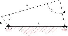
The linkage positions shown below with an angle α = 0 o and 180 o
has a near infinite mechanical advantage. These positions are referred to as toggle
positions. These positions allow the 4 bar linkage to be used a clamping tools.
The angle β is called the "transmission angle".
As the value sin(transmission angle) becomes small the mechanical advantage of the linkage approaches zero.
In these region the linkage is very liable to lock up with very small amounts of friction. When using four bar linkages
to transfer torque it is generally considered prudent to avoid transmission angles below 450 and 500.
In the figure above if link (d) is made the driver the system shown is in a locked position. The system has no toggle positions
and the linkage is a poor design
Freudenstein's Equation
This equation provides a simple algebraic method of determining the position of
an output lever knowing the four link lengths and the position of the input lever.
Consider the 4 -bar linkage chain as shown below..
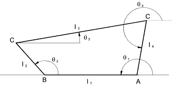
The position vector of the links are related as follows
l 1 + l 2 + l 3 + l 4 = 0
Equating horizontal distances
l 1 cos θ 1 +
l 2 cos θ 2 +
l 3 cos θ 3 +
l 4 cos θ 4 = 0
Equating Vertical distances
l 1 sin θ 1 +
l 2 sin θ 2 +
l 3 sin θ 3 +
l 4 sin θ 4 = 0
Assuming θ 1 = 1800
then sin θ 1 = 0 and cosθ 1 = -1 Therefore
- l 1 +
l 2 cosθ 2 +
l 3 cosθ 3 +
l 4 cos θ 4 = 0
and ..
l 2 sin θ 2 +
l 3 sin θ 3 +
l 4 sin θ 4 = 0
Moving all terms except those containing l 3 to the RHS and Squaring both sides
l 32 cos 2 θ 3 =
(l 1 - l 2 cos θ 2 - l 4
cos θ 4 ) 2
l 32 sin 2 θ 3 =
( - l 2 sin θ 2 -
l 4 sin θ 4) 2
Adding the above 2 equations and using the relationships
cos ( θ 2 - θ 4 )
= cos θ 2 cos θ 4 +
sin θ 2sin θ 4 ) and
sin2θ + cos2θ = 1
the following relationship results..

Freudenstein's Equation results from this relationship as
K 1 cos θ 2 +
K2 cos θ 4 + K 3 = cos ( θ 2 - θ 4 )
K1 = l1 / l4
K2 = l 1 / l 2
K3 = ( l 32 - l 12 - l 22 - l 2 4 ) / 2 l 2 l 4
This equation enables the analytic synthesis of a 4 bar linkage.
If three positions of the output lever are required corresponding to the angular position
of the input lever at three positions then this equation can be used to determine the
appropriate lever lengths using three simultaneous equations...
Velocity Vectors for Links
The velocity of one point on a link must be perpendicular to the axis of the link, otherwise
there would be a change in length of the link.
On the link shown below B has a velocity of vAB = ω.AB perpendicular to A-B. "
The velocity vector is
shown...

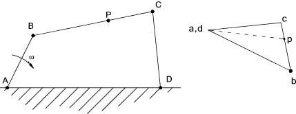
Considering the four bar arrangement shown below. The velocity vector diagram is built up as follows:
- As A and D are fixed then the velocity of D relative to A = 0 a and d are located at the same point
- The velocity of B relative to a is vAB = ω.AB perpendicular to A-B. This is drawn to scale as shown
- The velocity of C relative to B is perpedicular to CB and passes through b
- The velocity of C relative to D is perpedicular to CD and passes through d
- The velocity of P is obtained from the vector diagram by using the relationship bp/bc = BP/BC
|
The velocity vector diagram is easily drawn as shown...
Velocity of sliding Block on Rotating Link
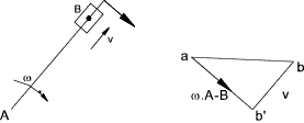
Consider a block B sliding on a link rotating about A. The block is instantaneously
located at B' on the link..
The velocity of B' relative to A = ω.AB perpendicular to the line. The velocity of B relative to B' = v.
The link block and the associated vector diagram is shown below..
Acceleration Vectors for Links
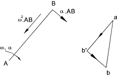
The acceleration of a point on a link relative to another has two components:
- 1) the centripetal component due to the angular velocity of the link.ω 2.Length
- 2) the tangential component due to the angular acceleration of the link....
|
The diagram below shows how to to construct a vector diagram for the acceleration components on a single link.
The centripetal acceleration ab' = ω 2.AB towards the centre of rotation.
The tangential component b'b = α. AB in a direction perpendicular to the link..
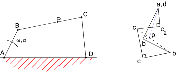
The diagram below shows how to construct an acceleration vector drawing for a four bar linkage.
- For A and D are fixed relative to each other and the relative acceleration = 0 ( a,d are together )
- The acceleration of B relative to A are drawn as for the above link
- The centripetal acceleration of C relative to B = v 2CB and is directed towards B ( bc1 )
- The tangential acceleration of C relative to B is unknown but its direction is known
- The centripetal acceleration of C relative to D = v 2CD and is directed towards d( dc2)
- The tangential acceleration of C relative to D is unknown but its direction is known.
- The intersection of the lines through c1 and c 2 locates c
|
The location of the acceleration of point p is obtained by proportion bp/bc = BP/BC and the absolute
acceleration of P = ap
The diagram below shows how to construct and acceleration vector diagram for a sliding block on
a rotating link..
The link with the sliding block is drawn in two positions..at an angle dω
The velocity of the point on the link coincident with B changes from ω.r =a b 1 to ( ω + dω) (r +dr) = a b 2
The change in velocity b1b2has a radial component ωr d θ and a tangential component ωdr + r dω
The velocity of B on the sliding block relative to the coincident point on the link changes from
v = a b 3 to v + dv = a b 4.
The change in velocity = b3b4 which has radial components dv and tangential components v d θ
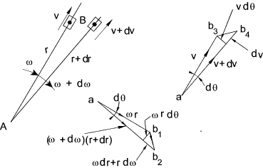
The total change in velocity in the radial direction = dv- ω r d θ
Radial acceleration = dv / dt = ω r d θ / dt = a - ω2 r
The total change in velocity in the tangential direction = v dθ + ω dr + r α
Tangential acceleration = v dθ / dt + ω dr/dt + r d ω / dt
= v ω + ω v + r α = α r + 2 v ω
The acceleration vector diagram for the block is shown below
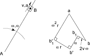
Note : The term 2 v ω representing the tangential acceleration of the block relative
to the coincident point on the link is called the coriolis component and results whenever
a block slides along a rotating link and whenever a link slides through a swivelling block
| 


