| |
Mechanics Index
Mohr's Circle
|
Background Notes
In considering plane stress i.e. stress in the x-y plane the z plane is assumed to be stress free Three dimensional stress analysis
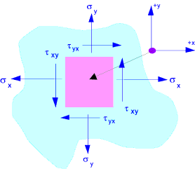
is similar in principle but a bit more complicated. The diagram below represents a small point in a solid which is under stress
in the x and the y direction. The point is in equilibrium so forces in the x direction are balanced as are forces in the y direction.
Also clockwise (cw) moments balance counter clockwise moments(ccw). Therefore τ xy = τ yx
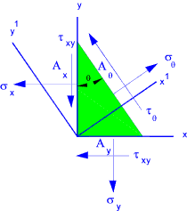
The figure below represents a two dimensional loading regime with a tensile stress (+ ve) σx in
the x direction and a tensile stress (+ve) σyin the y direction.
A counterclockwise (-ve)shear stress τ xy on the x surface and a balancing clockwise
shear stress (+ve)shear stress τ xy on the y surface..
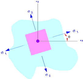
If the x-y axes is rotated the various stress will also change. There is an angle
θ at which normal stresses will be a maximum and minimum. At this
angle there will be zero shear stress. These stresses are called the principal stresses.
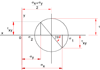
Mohr's Circle is a simple graphical method of showing stresses and strains
within objects subject to loading enabling convenient visualisation
and evaluation of developed stresses and strains at different axes to the
generating loads. i.e. The graphical representation of the variation of the
stress and strain components resulting from rotating coordinate axes. Mohr's
circle can be used for convenient representation of 3 dimensional stress strain distributions.
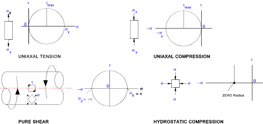
Mohr's circles representing different stress regimes are shown below:
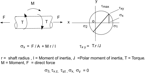
For a typical application of a shaft subject to direct stress, torque, and a bending moment the mohrs circle is as follows
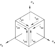
Three Dimensional Systems When completing two dimensional assessments it should be recognised that solids are actually three dimensional and the stress distribution is actually as shown below..
There are always three principal stresses - (though one of the principal stress may be zero). Some typical three dimensional mohr's circle diagrams are shown below..
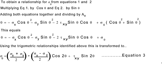
Theory The following Trigometric relationships apply. Cos θ2 =(1 + Cos (2θ) ) /2
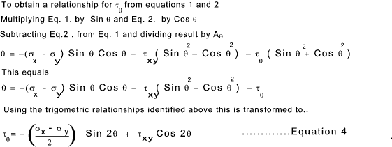
Analysing the resulting stresses when rotating the axes
Consider a rotated small element A x = A θ. Cos (θ )
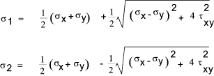
By differentiating σθ with respect to θ and equating to zero the conditions for the maximum and minimum stress can be determined
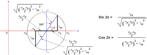
The the two solutions satisfying this condition are illustrated in the figure below.
By comparing equations 4 and 5 above it is clear that at the angle resulting in the principal
stresses (max and min) the shear stresses are 0...
|
Links to Mohr's Circle
|
|
Mechanics Index
