Any elastic material which is subject an applied force is deformed.
There are clearly defined relationships between the applied forces and the resulting deformations. This
page indentifies these relationships.
Direct Stress
The average stress on a bar under a tensile load is defined as the force /the cross section
area at right angles to the direction of the force.
σavg = F /A
The actual stress at a point a tensile load established by considering a small
area Δ A with ΔF representing the normal force transmitted by the area.
The stress is Δ Force /Δ Area as ΔA ->0
area at right angles to the direction of the force.
σ = limΔA ->0 ΔF /ΔA = dF /dA
Tensile stress is generally considered positive and compressive stress is negative/
Direct Strain
The average normal strain experienced by a bar under tensile load is simply defined
as the average change in length /original length
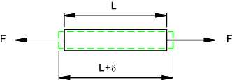
εavg = δavg /L
The actual strain at a point as a result of a tensile load is
established by considering a small length change Δ δ
of small part of the original length ΔL .
The strain is Δ δ as ΔL ->0 .
ε = limΔL ->0 Δ δ /Δ L = dδ /dL
Strain due to tensile stresses are generally considered positive and those resulting from
compressive stress are negative/
Poissen's Ratio
The sketch below shows a very simplified view of an microscopic element of
material subject to direct stress under three loading conditions. There are assumed
to be no shear stresses.
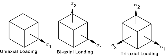
When an element is stressed in the x direction there is a proportional strain in the x direction.
The length increases due to tensile length. In addition the section reduces in a proportional way. The ratio
of lateral strain to axial strain has been demonstrated to be proportional and the proportionality constant
is called "Poissens ratio" υ. This constant is different for different materials
υ = lateral strain /axial strain
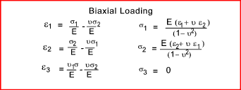
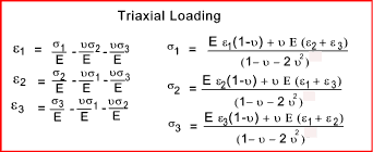
The table below identifies the stress strain relationships for each of the three
loading systems as illustrated.

Shear Stress
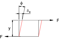
If an applied load consists of two equal and opposite forces which are not in
the same line then the material being loaded will tend to shear as shown.
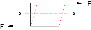
If area of the surface under shear load is A and the shearing force is F then the average shear stress
is
τ av = F /A
Any section x-x between the tangential forces will experience the same shear stress. The shear stress is tangential to the area on which it acts. Dowels, keys, and rivets
are generally designed for withstanding shear loads. A shaft in torsion is mainly
transmitted torque by shear loading.
The actual shear stress at a point due to a shear load is
established by considering a small area Δ A with ΔF
representing the tangential force transmitted by the area.
The shar stress is Δ Force /Δ Area as ΔA ->0
area at right angles to the direction of the force.
τ = limΔA ->0 ΔF /ΔA = dF /dA
Complementary Shear Stress
Consider a small element under a shear stress condition. For the element
to be in equilibrium the horizontal forces and the vertical forces balanced and the sum
of the moments on the area should also be zero.
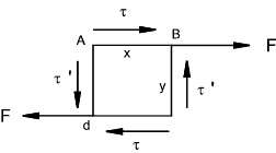
The element assumed to be 1 unit thick and the couple resulting from the shear stress τ = τ .x.y.
For equilibrium there must be a couple from a complementary shear stress τ ' this resulting couple will be τ '. y.x.
τ .x.y = τ ' y.x.... Therefore ....τ = τ '
For every shear stress the is an equal complementary shear stress on planes at right angles. The direction of the shear stresses on
an element is either both towards or both away from the corners.
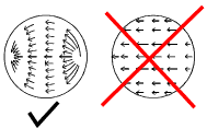
An important consequence of this is that near any free surface with no external applied forces, the shear stress on any cross section
must be parallel to the boundary. A round section subject to pure lateral shear is subject to shear stress as shown below.
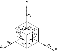
The figure below shows a stress element and illustrates the method of identifying normal and shear stresses. The directions
are all positive
