Introduction
A long structural member subject to a compressive load is called a strut.
Struts with large cross sections compared with the length generally fail under
compressive stress and the conventional failure criteria apply. When the cross
section area is not large compared to the length i.e the member is slender, then the
member will generally fail by buckling well before the compressive yield strength
is reached.
The notes below relate to uniform straight members made from homogeneous engineering
materials used within the elastic operating range. It is assumed that an end load is
applied along the centroid of the ends. The strut will remain straight until
the end load reaches a critical value and buckling will be initiated. Any increase in load will result in a
catastrophic collapse and a reduction in load will allow the strut to straighten.
The value of the critical load depends upon the slenderness ratio and the end fixing
conditions. The slenderness ratio (λ )is defined as the effective length =Le / the
least radius of gyration = k of the section The principal end fixing conditions are
listed below

The principal end fixing conditions are
listed below
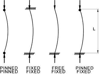
- Pinned (hinged) at both ends
- Fixed (built-in) at both ends
- Fixed at one end and free at the other
- Fixed at one end and pinned at the other
|
Symbols
A = Area (m2)
k = radius of gyration of section (m)
W = End force on strut. (N)
We = Euler end force on strut. (N)
WR = Rankine end force on strut. (N)
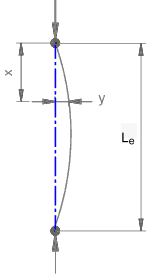
L = Length of strut (m )
Le = effective length of strut (m)
x = position along strut
y = strut deflection at x
R= Radius of bend (m)
Pc= Allowable stress (N/m2 )
M = moment (Nm)
|
I = Moment of inertia (m4)
σ e = Euler stress (N/m2)
σc = compressive failure stress (N/m2)
σR = compressive failure stress (N/m2)
λ = slenderness ratio
E = modulus of elasticity (Young's Modulus) (N/m2)
Wc = Compressive failure Load
We = Euler Load
|
Eulers Theory
The simple analysis below is based on the pinned-pinned arrangement. The other arrangements
are derived from this by replacing the length L by the effective length Le.
For the pinned-pinned case the effective length Le = L.
For the Fixed -Fixed case the effective length Le = L/2.
For the Fixed-Free case the effective length Le = L x 2.
For the Fixed-Pinned case the effective length Le approx. L x 0,7.
Curvature
Quick derivation for curvature (1/R)

Beam equation
Note: The derivation below is based on a strut with pinned ends. A similar method can be used
to arrive at the Euler loads for other end arrangements which will confirm the basis for the factors in arriving at the
equivalent length b.
M / I = σ / y = E / R
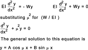
When x = 0 y = 0 and therefore A cos μ.0 + B sin μ.0 = A = 0 therefore A = 0
When x = b , y = 0 and so B sin μb = 0.
B cannot be 0 because there would be no deflection and no buckling which is contrary to experience.
Hence sin μ Le = 0. therefore μ Le = 0, π, 2π, 3 π etc
(W/EI) Le 2 = π 2,
4.π 2, 9.π 2 etc
therefore
W = π 2 E.I / Le2 ,
π 2 E.I / (Le / 2) 2,
π 2 E.I / (Le / 3) 2
The lowest value of W results from π 2 E.I / Le2
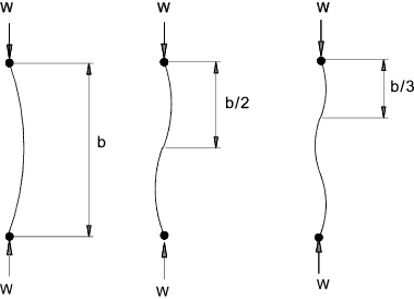
The lowest value of W resulting from this procedure is called the Euler load
(We ) and failure of long slender beams due to buckling results from this
much earlier than failure due pure compression.
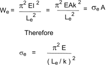
As the moment of inertia I = A.k 2 and the end force W = σ A. The formula
can be rewritten
Important Note: The value of I and the equivalent value of k are assumed to be the minimum values for the section
under consideration
Validity of Eulers theory
This theory takes no account of the compressive stress. For a metal with a compressive
strength of less than 300 N/mm2 and a Young's Modulus of about 200 kN/mm2.
The strut will tend to fail in compression if the slenderness ratio (Le/ k) is less than 80.
Therefore for steel Eulers equation is not reliable for slenderness ratios less than
80 and really should not be used for slenderness ratios less than 120.
Rankine - Gordon Criteria
This criteria is based on experimental results.
This criteria suggests that the strut will fail at a load given by.
1 / W R = 1 / Wc + 1 / We
Wc = Compressive failure Load
We = Euler Load

Substituting c = σ c / ( π 2 E) - A constant for each material

This design criteria provides more accurate buckling loads than the euler theory
especially at lower slenderness ratios. At higher slenderness ratios
the two methods yield similar results. The experimental values for c are not in direct
agreement with the theoretical values. BS 449-2:1969 includes tables for the safe working stresses for
all slenderness ratios and a range of steel specifications.
Table showing approximate values of c
| Material | c |
| Mild Steel | 1/7500 |
| Wrought Iron | 1/9000 |
| Cast Iron | 1/1600 |
| Wood | 1/3000 |
Perry Robertson formula (BS 449-2 )
Important ..The notes and equation and table below is provided for general guidance. For detail structural
design it is important to refer to the identified standards. The information below is
only a trivial relative to the level of detail provided in the standard.
The equation below is used as the basis for the allowable design stresses as
provided in the relevant tables in BS 449 and is considered the most reliable of the methods available
for buckling loads for long slender struts..The equation below is similar to that provided in appendix B of BS 449 part 2 :1969

pc = Permissible average compressive stress
k2 = Load coefficient ( normally 1,7)
σ y = Yield stress N/m2
σ y = Euler stress N/m2
η = 0,3 ( Le / 100k )2
Table of Allowable stress values pc for structural steels
The table is based on table 17 in BS 449 and relates to BS 4360 steels. Which is superseded by BS EN 10025 the grades of which are
identified ().
| |
Grade 43 (S275) |
Grade 50 (S355) |
Grade 55 (S420) |
|
|
Grade 43 (S275) |
Grade 50 (S355) |
Grade 55 (S420) |
| Le/ k |
MPa |
Le/ k |
MPa |
| 0 |
170 |
215 |
265 |
95 |
89 |
100 |
108 |
| 5 |
167 |
212 |
262 |
100 |
82 |
92 |
99 |
| 10 |
165 |
210 |
258 |
110 |
71 |
78 |
83 |
| 15 |
162 |
207 |
255 |
120 |
62 |
67 |
71 |
| 20 |
159 |
205 |
252 |
130 |
54 |
58 |
61 |
| 25 |
157 |
202 |
248 |
140 |
47 |
50 |
53 |
| 30 |
154 |
200 |
245 |
150 |
41 |
44 |
46 |
| 35 |
152 |
197 |
241 |
160 |
37 |
39 |
41 |
| 40 |
150 |
193 |
236 |
170 |
33 |
35 |
36 |
| 45 |
147 |
189 |
230 |
180 |
29 |
31 |
32 |
| 50 |
144 |
184 |
222 |
190 |
26 |
28 |
29 |
| 55 |
139 |
177 |
212 |
200 |
24 |
25 |
26 |
| 60 |
135 |
169 |
200 |
210 |
22 |
23 |
24 |
| 65 |
129 |
160 |
186 |
220 |
20 |
21 |
22 |
| 70 |
123 |
150 |
172 |
230 |
18 |
19 |
20 |
| 75 |
116 |
140 |
157 |
240 |
17 |
18 |
18 |
| 80 |
109 |
129 |
143 |
250 |
16 |
16 |
17 |
| 85 |
102 |
119 |
130 |
300 |
11 |
11 |
12 |
| 90 |
95 |
109 |
118 |
350 |
8 |
8 |
9 |
|