Introduction
Springs used to apply torque or store rotational energy are generally called
torsion or double torsion springs. Torque by definition is a force
that produces rotation. A torsion spring exerts a force (torque) in
a circular arc, and the arms rotate about the central axis. The stress
is in bending, not in torsion. It is customary to specify torque
with deflection or with the arms at a definite position.
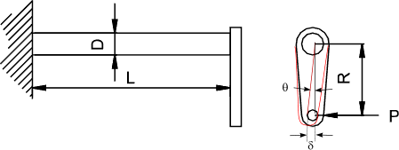
Torsion bar
The torsion bar is the simplest form or torsion beam.
It comprises a solid or hollow bar which is stressed in torsion within its elastic limit.

Nomenclature
|
P = Force on lever arm (m).
T = Torque resulting from force = PR (Nm)
R = lever radius (m)
D= bar outside diameter (m)
d= bar inside diameter (m)
L = bar length (m)
kL = Linear Spring rate || Force based = P / δ (Nm) ....Torque Based = T / δ (N)
kA = Angular Spring rate || Forced based = P / θ (N)....Torque Based = T / θ (Nm)
G = Modulus of Rigidity (N/mm2)(m)
τ = Allowable shear stress
θ = Deflection (radians)
δ = Linear Deflection= θ. R(m )
|
Solid Bar
| Force Based | Torque Based |
|
Deflection δ = 32PR2 L /( π GD 4 )
Angular Deflection θ = 32PR L /( π GD 4 )
Linear spring rate k L = P / δ = πG D4 /(32R 2 L)
Angular spring rate k A = P / θ =πG D4 /(32RL)
Maximum Load Pmax = π D3 τ /(16 R)
|
Deflection δ = 32TRL /( π GD 4 )
Angular Deflection θ = 32TL /( π GD 4 )
Linear spring rate k L = T / δ = πG D4 /(32RL)
Angular spring rate k A = T/ θ = πG D4 /(32L)
Maximum Torque Tmax = π D3 τ /16
|
Hollow Bar
Solid Bar
| Force Based | Torque Based |
|
Deflection δ = 32PR2 L /( π G(D 4 - d 4 )
Angular Deflection θ = 32PRL /( π G(D 4 - d 4 )
Linear Spring Rate k L = P / δ= πG (D 4 - d 4) /(32R 2 L)
Angular Spring Rate k A = P / θ = πG (D 4 - d 4) /(32RL)
Maximum Load Pmax = π(D 4 - d 4) τ /(16DR)
|
Deflection δ = 32TR L /( π G(D 4 - d 4 )
Angular Deflection θ = 32TL /( π G(D 4 - d 4 )
Linear Spring Rate k L = T / δ= πG (D 4 - d 4) /(32RL)
Angular Spring Rate k A = T / θ = πG (D 4 - d 4) /(32L)
Maximum Torque Tmax = π(D 4 - d 4) τ /(16D)
|
Torsion Spring
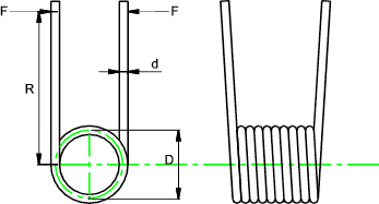
A typical torsion helical spring is shown below. There are a wide variety of
coil end configurations to suit different applications and a torsion spring is usually
positioned on a shaft. The coils are usually close wound as are tension springs
but they generally do not have any initial tension unlike tension springs.
The primary stress induced in torsion spring is a bending stress in the wire . This
is not the case for the tension and compression helical springs for which the primary stress
is a torsional (shear) stress. During forming residual stresses are built up in the winding
process. These residual stresses are in the same direction but of opposite sign
to the working stresses resulting when the spring is loaded causing the coils to tighten. Torsion
springs are stronger as a result and they are often designed to work at, or above the yield strength.

Nomenclature
|
C = Spring Index D/d
d = wire diameter (m)
D = Spring diameter (m)
Di = Spring inside diameter (m)
Dil = Spring inside diameter (loaded ) (m)
E = Young's Modulus (N/m2)
I = Moment of Inertia of wire(m4 )
F = applied Force (N)
G = Modulus of Rigidity (N/m2)(m)
ka = Angular spring rate (stiffness) M /θ (Nm /radian)
L = length (m)
M = Moment (Torque) = RF (Nm)
n = Number of active coils
y = distance from neutral axis to outer fibre of wire (m)
τ = Allowable shear stress (N/m2 )
θ = Deflection (radians)
σ = Bending stress (N/m2 )
|
Note: metres (m) have been shown as the units of length in all of the variables above
for consistency. In most practical calculations milli-metres will be more
convenient.
Torsion Spring Formulae
The spring stress concentration factors Ki =

The maximum bending stress is at the inner fibre of the coil and equals

The angular spring rate ka =

Torsion springs are often used over shafts. It is important that the spring
inside diameter, when fully loaded is no t equal to, or less than the shaft diameter. If this happens
the spring will fail. The inside diameter of the loaded tension spring is

| 

