Liquid Lubrication
Lubrication is fundamental to the operation of all engineering machines. It is required
to minimise friction, wear and also provides a cooling function and a surface protection
function.
A liquid film lubrication regime can be hydrodynamic or hydrostatic. In hydrodynamic bearings
the fluid is introduced into the bearing surfaces by the action of the bearing. In hydrostatic
bearing the fluid is introduced under pressure from an external source.
Liquid lubrication in machines is normally hydrodynamic. An oil film is formed between
the two sliding surfaces separating them and providing a low sliding friction. However this mechanism is only active during the sliding movement. At the start
and at the termination of movement the oil film is not present. At these times wear can take place.
Hydrodynamic lubrication is present in linear motion (slideways) and in rotational motion (journals).
An important property of a liquid used for lubrication is its viscosity.. The viscosity
of a fluid is its resistance to shear. The friction in a lubricated bearing
is directly related to the fluid viscosity. Notes and links providing viscosity information
is provide on this website ....Viscosity
The design of a liquid lubricated bearing system must include cosideration of a number of associated factors as listed below:
- Selection of oil/grease grade
- Design of the lubrication system - oil bath, forced circulation, oil wick , porous bearings etc
- Ensure the cleanliness of the oil - regular oil replacement , continuous filtration etc
- Cooling of the oil to remove generated heat- natural cooling, using coolers etc
- Oil degeneration in use
|
It is not possible to address these factors on this page.. Please refer to the links provided below
Bearing Coefficient of Fricton and power requirement..
Petroff's equation provides an friction value for an unloaded journal bearing i.e with
the shaft concentric with the journal. This assumes no end load and does not allow
for end leakage..
f = 2 . p 2 . (m . n / p ) . r / c
Torque to rotate shaft .. T (Nm)
= W. f .r
= W.[ 2 . p 2 . (m . n / p ) . r / c ] . r
= W.[ 2 . p 2 . (m . n . L. 2. r / W ) . r / c ] .r =
4.p 2.r3.m . n .L / c
Power to rotate shaft... = T.ω = T.2.p .n
> P (Watts) =
8 . p 3 .n 2 . r 3 . L . m / c
= p 3 .n 2 . d 3 . L . m / c
- P = Power (Watts = N.m /s )
- d = Bearing radius (m)
- r = Bearing radius (m)
- L = Bearing length (m)
- A = Bearing projected Area = L . D (m 2)
- W = Bearing Radial Load (N))
- p = Bearing pressure over projected Area = W / A = W /(L.2.r)(Pa)
- m = Absolute Viscosity (Pa . s )
- c = radial clearance ( m )
- t = axial clearance ( m )
- n = Rotational Speed revs /s
- r1 = Inner radius of thrust bearing (m)/li>
- r2 = Outer radius of thrust bearing (m)/li>
|
The equivalent power for a rotating thrust bearing ...
P (Watts) = 2 . p
3 .n 2 . m . ( r2
4 — r1 4 ) / t
Hydrostatic Lubrication
Journal and thrust and linear bearings can be hydrostatic in that the load carrying capacity results
from externally generated lubricant pressure. These type of bearing do not depend on
the relative motion of the bearing surfaces for lubrication and so they are effective at zero and
very low velocities. This type of lubrication does not involve the necessity of metal
contact during start-up and shut down.
Hydrostatic lubrication systems are generally expensive to engineer and are liable to problems
with controlling the lubrication supply
Hydrodynamic Lubrication
Note; Hydrodynamic Lubrication is extremely complex.
These notes provide only outline explanations of the principles involved...
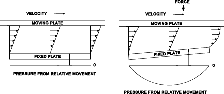
In hydrodynamic lubrication the fluid is assumed not to slip at the interface with the
bearing surfaces i.e. the fluid in contact with the bearing surfaces moves at the same velocity as the surface.
Over the thickness of the fluid there is a velocity gradient depending on the relative
movement of the bearing surfaces. If the bearing surfaces are parallel (or concentric ) the action
motion of the lubricant will not result in a pressure which could support any bearing load. However
if the surfaces are at a slight angle the resulting lubrication fluid velocity gradients will be such that
a pressure results from the wedging action of the bearing surfaces... Hydrodynamic lubrication depends
upon this effect... Note; This principle is similar to the lift in water skiing / aqua planing ..
Lubrication of journal bearings
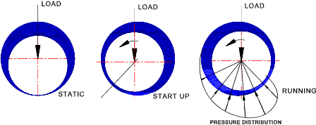
The operation of hydrodynamic lubrication in journal bearings is illustrated below. Before the rotation commences
the shaft rests on the bearing surface. When the rotation commences the shaft moves up the bore until an equilibrium condition
is reached when the shaft is supported on a wedge of lubricant. The moving surfaces are then held apart by the pressure generated
within the fluid film. Journal bearings are designed such that at normal operating conditions the continuously generated fluid pressure supports
the load with no contact between the bearing surfaces. This operating condition is known as thick film lubrication and results in a very
low operating friction and extremely low bearing load
Boundary lubricating conditions occur when the lubricant film is insufficient to prevent surface contact. This occurs at rotation start-up, a slow speed
operation or if the load is too heavy. This regime results in bearing wear and a relatively high friction value. If a bearing is operated under
boundary lubricating conditions special lubricants are needed.
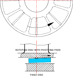
The operation of hydrodynamic lubrication for thrust bearings is enabled by various design options including tilting
pads, taper lands and step bearings. The tilting pads provide the most ideal Hydrodynamic lubrication conditions
as shown on the figure below..
Factors Affecting Hydrodynamic Lubrication..
It is generally desirable to achieve hydrodynamic lubrication in bearings or the following reasons;
- Very low friction factor
- Virtually zero wear results
- Lower cost compared with hydrostatic lubrication
|
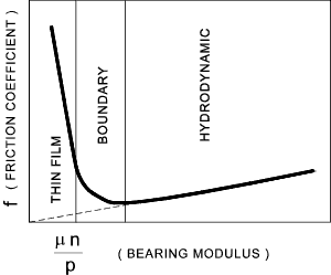
Hydrodynamic lubrication depends on at least three of dimensionless numbers ...
( m .n / p ) , ( D / h ) , and (L/D)
The relationship between the bearing friction coefficient and the bearing modulus
is shown in the figure below
| Equipment |
Bearing |
Max Pressure |
m |
m n /p |
| MPa |
Pa. s |
| Automobile /Aircraft Engines |
Main |
5 - 12 |
0,007 |
3,67 x 10⁻⁸ |
| Crankpin |
10-23 |
0,008 |
2,50 x 10⁻⁸ |
| Wrist pin |
14 -35 |
0,008 |
|
| Gas and Oil Engines |
Main |
3.5 - 8 |
0,02 |
5,00 x 10⁻⁸ |
| Crankpin |
7 -12 |
0,04 |
2,50 x 10⁻⁸ |
| Wrist pin |
8-14 |
0,065 |
|
| Marine Engines |
Main |
3.5 |
0,03 |
5,00 x 10⁻⁸ |
| Crankpin |
4 |
0,04 |
3,67 x 10⁻⁸ |
| Wristpin |
10 |
0,05 |
|
| Stationary steam engines |
Main |
1,5 - 3 |
0,015 -0,06 |
5,00 x 10⁻⁸ |
| Crankpin |
4 -10 |
0,03 -0,08 |
1,50 x 10⁻⁸ |
| Wristpin |
12 |
0,025 -0,06 |
|
| Reciprocating pumps and compressors |
Main |
2 |
0,03 |
7,33 x 10⁻⁸ |
| Crankpin |
4 |
0,05 |
3,67 x 10⁻⁸ |
| Wristpin |
7 |
0,08 |
3,67 x 10⁻⁸ |
| Steam Turbines |
Main |
0,5 - 2 |
0,002-0,016 |
25,0 x 10⁻⁸ |
| Rotary Pumps and Motors |
Shaft |
0,5 -1.5 |
0,025 |
50,0 x 10⁻⁸
|
A design constraint to keep thick film (full hydrodynamic)
is to ensure the bearing modulus (m n /p ) >= 1.09 x 10⁻⁹
Approximate Determination of friction of journal bearings with hydrodynamic lubrication
McKee established the following relationship using small bearings . This does not allow for end leakage
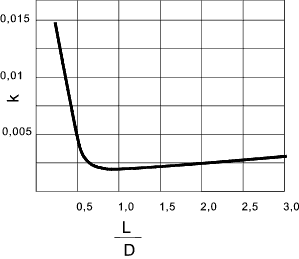
f = 19,56 . ( m .n / p ). ( D /C) + k
k is obtained from the diagram below but can be approximated as 0.002 over an L/D ration 0 0.75 - 2.6
Sommerfeld Number
The Sommerfeld Number is a dimensionless parameter used in lubrication analysis.
S = ( m .n / p ). ( D /C) 2
This parameter has been used as the abscissa for a number of design curves. The ordinate can
be selected to allow the friction value, film thickness, oil leakage, temperature rise etc
to be determined. Design curves have been produced of various variables against the Sommerfeld using computer
techniques by A.A Raimondi and J.Boyd of Westinghouse Research Labs(ASLE Transactions Vol 1 No 1 April 1958).
These graphs include compensation for end leakage and eccentricity.
The illustrative design curve has been included below. Detailed
journal and thrust bearing designs should be completed using the relevant specialist
sources of information or software..
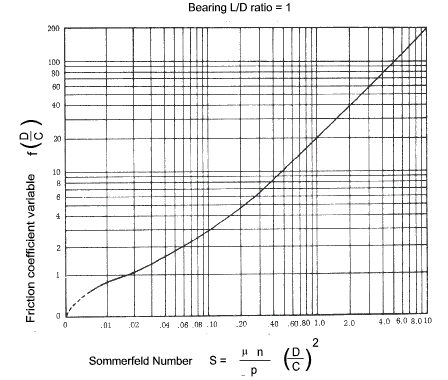
In comparing the value of f(D/C) resulting from the Petroff, McKee and the Raimondi-Boyd data the
values are in close agreement for the higher values of the Sommerfeld number (above 0.5) i.e the
lightly loaded bearings..
Journal clearances -
The table below provides some typical diametrical clearances for journal bearings under steady
loads and for hydrodynamic lubrication.
These are very crude values. Serious journal bearing design should include a
detailed analysis. The diametric clearance is the journal diameter - the shaft diameter
| Speed Range | Shaft Diameter | Diametrical Clearance |
| | mm | mm |
| Below 600 RPM | 25 | 0,025 - 0,05 |
| Above 600 RPM | 25 | 0,03 - 0,10 |
| Below 600 RPM | 40 | 0,03 - 0,08 |
| Above 600 RPM | 40 | 0,05 - 0,12 |
| Below 600 RPM | 50 | 0,04 - 0,09 |
| Above 600 RPM | 50 | 0,06 - 0,14 |
| Below 600 RPM | 80 | 0,05 - 0,11 |
| Above 600 RPM | 80 | 0,08 - 0,17 |
| Below 600 RPM | 100 | 0,06 - 0,13 |
| Above 600 RPM | 100 | 0,09 - 0,20 |
| Below 600 RPM | 125 | 0,07 - ,14 |
| Above 600 RPM | 125 | 0,10 - 0,22 |
| Below 600 RPM | 150 | 0,08 - 0,15 |
| Above 600 RPM | 150 | 0,12 - 0,24 |
| Below 600 RPM | 200 | 0,09 - 0,17 |
| Above 600 RPM | 200 | 0,14 - 0,27 |
|
