Introduction
The development work on the Eurocodes was initiated in 1975 and although progress has been very slow the full set of eurocodes
and the associated various National Annexes, required for local code variations, have now been issued for use. These codes
relate to the construction industry and are produced by the European Committee for Standardization (CEN), and replace existing national standards in 28 countries. The codes include the principles, rules and
recommended values for ultimate limit design. However safety , durability and economy have be derogated to member states and are included in National Annexes.
The Eurocodes are proving to be the most comprehensive coding of structural and civils design in the world.
This page of the website includes outline notes introducing the Eurocodes. The notes are simply sufficient to provided background information for
engineers /students to start off on a course of study or a project. References and standards are listed which should be used for
detail design work. Links are provided which include, in some detail, information relevant to the Eurocodes.
The notes on this page specifically address actions and the related partial margins .
The construction materials and their related partial safety margins are addressed on the relevant linked pages.
Eurocodes
An outline list of the available eurocodes, but not their subsections or associated standards, are listed below.
BS EN 1990 Eurocode 0: Basis of structural design
BS EN 1991 Eurocode 1: Actions on structures
BS EN 1992 Eurocode 2: Design of concrete structures
BS EN 1993 Eurocode 3: Design of steel structures
BS EN 1994 Eurocode 4: Design of composite steel and concrete structures
|
BS EN 1995 Eurocode 5: Design of timber structures
BS EN 1996 Eurocode 6: Design of masonry structures
BS EN 1997 Eurocode 7: Geotechnical design (foundations)
BS EN 1998 Eurocode 8: Design of structures for earthquake resistance.(seismic design)
BS EN 1999 Eurocode 9: Design of aluminium structures
|
Terminology introduced with the Eurocodes
Action = Imposed load
Effect of Action = Resulting stress, strain, deflection,rotation
Permanent Action = Dead Load
Variable Action = Live Load
Execution = Construction process
Limit state = state at which the structure no longer fulfill the relevant design criteria.
Ultimate limit state (ULS) = states associated with collapse or similar structural failure.
Serviceability Limit state(SLS) = state such that the structure remains functional for its intended use subject to routine loading.
Ultimate Limit States
The Eurocodes are based on ultimate limit state design.
The Ultimate limit states are divided into the following
categories:
EQU Loss of equilibrium of the structure.
STR Internal failure or excessive deformation of the
structure or structural member.
GEO Failure due to excessive deformation of the
ground.
FAT Fatigue failure of the structure or structural
members.
These ultimate states are considered in different combinations in structural detail design.
In geotechical design ultimate limit states for resistance to uplift(UPL) and seepage ((HYD) have also to be considered.
The notes on this website only relate to the STR ultimate limit state.
Serviceability Limit State
Serviceability Limit state(SLS) is the design state such that the structure remains functional for
its intended use subject to routine loading. This affects such situations as doors / windows failing to open due to structural
deformation. It relates to factors others than the building strength that renders the buildings unusable. Serviceability
limit state design of structures includes consideration of durability, overall stability, fire resistance, deflection, cracking and
excessive vibration. This website only considers this limit state in outline.
Verification for serviceability limit states in the ground or structional section or interface shall be such that
Ed =< Cd
Ed = The design value of the effect of actions such as internal force , moment or
vectorial representation of several internal forces or moments.
Cd = Nominal value or function of certain design properties of materials- (related to serviceability limit state
Ultimate limit state design
There are a number of criteria for limit state design and various categories generally need to be considered.
As a basic example of the principle involved when considering a limit state of rupture or excessive deformation of a section or connection
(STR ) it shall be verified that :
Ed ≤ Rd
Ed = The design value of the effect of actions such as internal force , moment or
vectorial representation of several internal forces or moments.
Rd = The design value of the corresponding resistance.
In simple English : the value of the product or the maximum expected forces or moments on a section
and the associated partial margins should be less than the characteristic value of the
strength of the sections divided by the relevant material partial safety margins.
Notes on the actions and their associated partial margins are found on this page and notes on the
Resistance values the associated partial margins are found on the web pages related to the construction materials
Selection of Eurocode symbols related to actions
| Symbol | Definition |
| Cd | Nominal value or function of certain design properties of materials |
| Ed | The design value of the effect of actions |
| Fk | Characteristic value of action |
| Fd | Design value of action |
| Gk | Characteristic value of permanent action |
| Gd | Design value of permanent action |
| Qk | Characteristic value of variable/imposed action (single value) |
| Rd | The design value of a component/system restistance. |
| γG | Partial factor for permanent action |
| γQ | Partial factor for variable action |
| ψ0 | Factor for combination value of variable action |
| ψ1 | Factor for frequent value of variable action |
| ψ2 | Factor for quasi-permanent value of variable action |
| ε | Combination factor for permanent actions |
| ξ | Reduction factor for unfavourable permanent actions |
Selection of Subscripts
| Subscript | Definition |
| A | Accidental |
| c | Concrete |
| m | Mortar |
| d | Design |
| E | Effect of action |
| fi | Fire |
| k | Characteristic |
| R | Resistance |
| w | Shear reinforcement |
| y | Yield strength |
Actions
The actions on a structure or a structural element comprise of permanent actions which are in principle unchanging through the
life of the structure and variable actions which are not fixed. The prime example of a permanent action is the weight of the construction
materials. Examples of variable actions include wind loading, occupancy loading, storage loading.
The design value of a permanent action or dead load is simply the product of the relevant
partial margin(γG) and the resultant load from the combination of all of the
static loads e.g. structure weight, weight of installed equipment(static) and services (empty).
Where the results of the verification are very sensitive to variations of the magnitude of a permanent action from place to
place in a structure, the unfavourable and favourable parts of this action shall be considered as individual actions
For each variable action there are four representative values.
The principal representative value is the characteristic imposed load e.g Qk . This
can be determined statistically or,where there is insufficient
data, a nominal value may be used. The other representative
values are obtained by applying to the characteristic value the factors
ψ0, ψ1 and ψ2 respectively .
These depend on the type of imposed load. The "combination" value (ψ0 Qk) of
an action is intended to take account of the reduced probability of the simultaneous
occurrence of two or more variable actions. The "frequent" value
(ψ1 Qk) is such that it should be exceeded only for a short
period of time and is used primarily for the serviceability limit
states (SLS) and also the accidental ultimate limit state (ULS).
The "quasi-permanent" value (ψ2 Qk) may be exceeded for a
considerable period of time; alternatively it may be considered
as an average loading over time. It is used for the long-term
affects at the SLS and also accidental and seismic ULS.
The following steps can be followed to determine the value of the variable actions:
- Identify the design situation (e.g. persistent, transient,
accidental)
- Identify all realistic actions.
- Determine the partial factors (see below) for each applicable
combination of actions.
- Arrange the actions to produce the most critical conditions
|
Actions may be forces ( loads applied to the structure or to the ground) and
displacements (or accelerations) that are imposed by the ground on the
structure, or by the structure on the ground. Actions may be permanent (e.g.
self-weight of structures or ground), variable (e.g. imposed loads on building
floors) or accidental (e.g. impact loads).
Design values of actions (F d ) are calculated using the general equation:
F d = γ F .f rep
where
F rep is the representative value of an action. This is generally equal to the characteristic F k value
of an permanent action or the leading variable action value , or it is equal to the ψ. F k of
an imposed (variable action).
γ f is the partial factor for an
action (or γ e , for the effect of an action).
..Fk = Gk and
γ f = γ g for a permanent action.
..Fk = Qk and
γ f = γ q for an imposed action.
The equation for the effect of an action should be
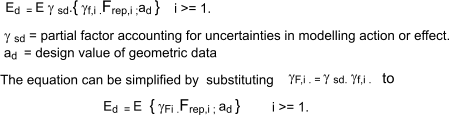
The general equation for the Effect of actions should be

The part of the equation inside the brackets represents the combination of permanent and variable actions
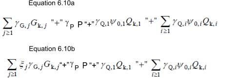
In BS EN 1990 one of a number of equations for load
combinations is equation 6,10
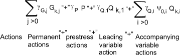
Note: The prestress term (γPP ) only applies to prestressed concrete applications
This is a quick, but conservative, method when compared to the alternative equations (6.10a and 6.10b)which are a little more complicated.
6.10b is generally the governing equation in the UK
Note: Again the prestress (γPP ) term only applies to prestressed concrete applications.
ξ = Reduction factor for unfavourable permanent actions G.
Recommended ψ values
| Action | ψ0 | ψ1 |
ψ2 |
| Imposed loads |
| Cat A Domestic residential areas |
0,7 | 0,5 | 0,3 |
| Cat B Office areas |
0,7 | 0,5 | 0,3 |
| Cat C congregation areas |
0,7 | 0,7 | 0,6 |
| Cat D shopping areas |
0,7 | 0,7 | 0,6 |
| Cat E storage areas |
1,0 | 0,9 | 0,8 |
| Cat F traffic areas vehicle weight < 30kN |
0,7 | 0,7 | 0,6 |
| Cat G traffic areas vehicle weight < 1600kN |
0,7 | 0,5 | 0,3 |
| Cat H roofs |
0,7 | 0 | 0 |
| Snow / windloads |
| Sites > 1000m above sea level |
0,7 | 0,5 | 0,2 |
| Sites < 1000m above sea level |
0,5 | 0,2 | 0 |
| Wind Loads |
0,6 | 0,5 | 0 |
Typical Action Scenarios.
It can also be seen
that the partial safety factors for actions depend on a number of other aspects including the category
of limit state as well as the effect of the action on the design situation under consideration.
| Persistent and transient design situations | permanent actions |
Leading variable actions | Accompanying variable actions |
| Unfavourable | Favourable | Unfavourable | Favourable | Main (if any |
Others |
| BS EN 1990(eq 6.10) |
γG.j,supGk,j,sup |
γGj,infGk,j,inf |
γQ,1Qk,1 |
- |
γQ,i ψ0,1 Qk,i |
| Combination of permanent and variable action ( Strength limit States STR ) |
| BS EN 1990(eq 6.10) |
1,35Gk |
1,0Gk |
1,5Qk.1 |
0 |
- | - |
| Combination of permanent and variable action and accompanying variable action ( Strength limit States STR ) |
| BS EN 1990(eq 6.10) |
1,35Gk |
1,0Gk |
1,5Qk.1 |
0 |
- |
1,5 ψ0.1 Qk.1 |
| Combination of permanent and variable action and accompanying variable action ( Equilibrium limit States EQU ) |
| BS EN 1990(eq 6.10) |
1,1 Gk |
0,9 Gk |
1,5Qk.1 |
0 |
- | 1,5 ψ0.1 Qk.1 |
Design value of a Material
The design value of the resistance of a material or ground property is given by the equation
X d = η.X k / γm
where
η = a scale factor covering uncertaintly, scaling , conditions etc.
X k = the characteristic value of a material (ground) property
γm = the partial factor for the material property.
Alternatively the scaling factor can be included within the characteristic value or
in the partial factor . In this case the equation reduces to
X d = X k / γM
where
γM = the partial factor for the material property including the scaling factor.
Design Resistance
The general equation for the resistance of the structure
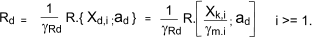
where
γRd = the partial factor for the resistance model uncertainty + geometric deviations.
Xd,i = design value of material property
ad = the design value of a geometric property e.g depth.
This can be simplified to
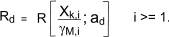
where
γM,i = γRd .γm,i
.
Design Life
The intended design life of the construction should be identified at the initial stage of the design process
table of design lives of buildings in accordance with BS EN 1990 clause 2,3
Design working life
category | Indicative design
working life
(years> |
Examples |
| 1 | 10 | Temporary structures |
| 2 | 10 to 25 | Replacable structures e.g. Gantry girders, bearings |
| 3 | 15 to 30 | Agricultural Builidng and similar structures |
| 4 | 50 | Buildings and other common structures |
| 5 | 100 | Monumental structures , bridges, civil engineering structures |
Unit Masses of Building Materials
Provided to enable estimates of dead loads
| Material |
Specific mass |
| Asphalt Roofing 2 layers, 19 mm thick |
42 kg / m2 |
| Bitumen roofing felts
Mineral surfaced bitumen
| 3.5 kg / m2 |
| Blockwork Solid per 25 mm thick stone aggregate ,
| 55 kg / m2 |
| Blockwork aerated per 25 mm thick
| 15 kg / m2 |
| Blockboard per 25 mm thick 12.5 kg / m.2
| 12,5 kg / m2 |
| Brickwork Clay, solid per 25 mm thick
| 55 kg / m2 |
| Brickwork medium density Concrete, solid per 25 mm thick
| 59 kg / m2 |
| Cast stone
| 2250 kg / m3 |
| Concrete Natural aggregates
| 2400 kg / m3 |
| Concrete Lightweight aggregates (structural)
| 2000- 1600 kg / m3 |
| Flagstones Concrete, 50 mm thick
| 120 kg / m2 |
| Glass fibre Slab, per 25 mm thick
| 2.0�5.0 kg / m2 |
| Gypsum panels and partitions Building panels 75 mm thick
| 44 kg / m2 |
| Lead Sheet, 2.5 mm thick
| 30 kg / m2 |
| Linoleum 3 mm thick
| 6 kg / m2 |
| Plaster Two coats gypsum, 13 mm thick
| 22 kg / m2 |
| Plastics sheeting (corrugated)
| 4.5 kg / m2 |
| Plywood per mm thick
| 0.7 kg / m2 |
| Reinforced concrete
| 2400 kg / m2 |
| Rendering Cement: sand (1:3), 13 mm thick
| 30 kg / m2 |
| Screeding Cement: sand (1:3), 13 mm thick
| 30 kg / m2 |
| Slate tiles (depending upon thickness and source)
| 24 �78 kg / m3 |
| Steel Solid (mild)
| 7850 kg / m3 |
| Corrugated roofing sheets, permm thick
| 10 kg / m2 |
| Tarmacadam 25 mm thick
| 60 kg / m2 |
| Terrazzo 25 mm thick
| 54 kg / m2 |
| Tiling, roof Clay
| 70 kg / m2 |
| Timber Softwood
| 590 kg / m2 |
| Hardwood
| 1250 kg / m2 |
| Water
| 1000 kg / m3 |
| Woodwool Slabs, 25 mm thick
| 15 kg / m2 |
Characteristic Values of Imposed load (occupancy )
Provided to enable estimates of imposed loads
1, Values based on BS EN 1991-1 table 6,2
| Categories of Loaded Areas | qk ( kN /m2 ) | Qk ( kN ) |
| Category A Domestic Areas | 1,5 to 2,0 | 2,0 to 3,0 |
| Category C1 Areas with Tables | 2,0 to to 3,0 | 3,0 to 4,0 |
| Category C2 Areas with fixed seats | 3,0 to to 4,0 | 2,5 to 7,0 |
| Category C3 Areas with freedom of movement | 3,0 to to 5,0 | 4,0 to 7,0 |
| Category C4 Areas for physical activities | 4,0 to to 5,0 | 3,5 to 7,0 |
| Category C5 Areas for large crowds (Arenas) | 4,5 to to 7,5 | 3,5 to 4,5 |
| Category D1 Shopping Areas (retails shops) | 4,5 to to 5,0 | 3,5 to 7,0 |
| Category D2 Shopping Areas (department stores) | 4,0 to to 5,0 | 3,5 to 7,0 |
Other Values
| Categories of Loaded Areas | qk ( kN/m2 ) | Qk ( kN ) |
| Boiler rooms , motor rooms , fan rooms inc. machinery weight | 7,5 | 4,5 |
| Kitchens , laundries. | 3,0 | 4,5 |
| Bedrooms | 2,0 | 1,8 |
| Toilets | 2,0 | - |
| Bars | 5,0 | - |
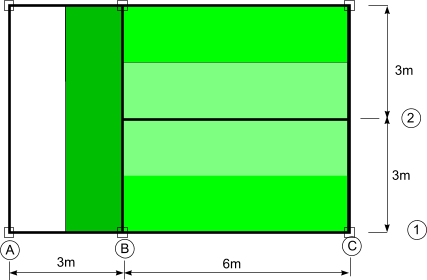
Example Loading Calculation
The floor as shown below has and overall depth of 250mm and is designed to
carry and imposed load of 2 kN / m 2 plus floor and ceiling finishes of 1 kN /m 2.
Calculate the design loads acting on
beams B1-C1, B2-C2 and B1-C3 and columns B1 and C1.
Assuming column heights are 3m and the beam weights are 70 kg/m-run and the column weights are 60 kg/m-run.
Unit weights of materials
Reinforced concrete :
The mass of reinforced concrete is 2400 kg/m3 (see above table ) for simplicity assume
gravitational constant gn = 10 m/ s2.
The unit
weight of the reinforced concrete is
2400 .10 = 24 kN/m3..
Steel beams :
The unit mass of beam 70 kg /m -run.
The unit weight of steel beam =
70 . 10 = 0,7 kN/m..
Columns :
The unit mass of column = 60 kg /m -run.
The unit weight of column =
60 . 10 = 0,6 kN/m..
Loading of separate items.
Slab permanent (dead ) load = Gk = (unit-weight . 0,25 ) + finishes ) Area = (6 + 1) Area = 7 .Area kN,
Slab variable (imposed) = Qk = 2. Area kN
Slab design load vertical load Vd_s = 1,35.Gk + 1,5.Qk
Beam permanent load (Gk ) = 0,7. Length kN
Beam design vertical load Vd_b = 1,35 . Gk
Column permanent load (Gk ) = 0,6 . Length kN
Column design vertical load Vd_c = 1,35. Gk
Design Vertical loads on beams....Assume slabs are simply supported
Beam B1-C1
This beam supports a uniformly distributed load resulting from 6m long x 1,5m width of slab + self weight of beam
Design load on beam B1-C1 = Vd_s +Vd_b
= 1,35. (7 . 6 . 1,5 ) + 1,5 .( 2 . 6 . 1,5 ) + 1,35.( 0,7 . 6 ) = 85,05 + 27 + 5,67 = 117,72kN
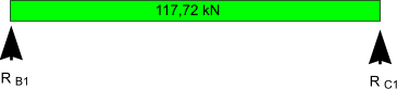
The reactions at B1 and C1 are equal = 117,72 /2 = 58,86kN
Beam B2-C2
This beam supports a uniformly distributed load on 6m long x 3 m width of slab + self weight of beam
Design load on beam B2-C2 = Vd_s +Vd_b
= 1,35. (7 . 6 . 3 ) + 1,5 .( 2 . 6 . 3 ) + 1,35.(0,7 . 6) = 170.1 + 54 + 5,67 =229,77
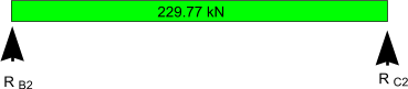
The reactions at B2 and C2 are equal = 229,77 /2 = 114,885kN
Beam B1-B3
This beam supports a uniformly distributed load from 6m long x 1,5 m width of slab + self weight of beam .
The beam also supporta a concentrated load at the centre resulting from beam B2-C3
Design loads on beam B1-B3
= 1,35. (7 . 6 . 1,5 ) + 1,5 .( 2 . 6 . 1,5 ) + 1,35.( 0,7 . 6 ) = 85,05 + 27 + 5,67 = 117,72kN
+ concentrated load of 114,9kN support force from B2-C2
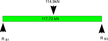
The reactions at B1 and B3 are equal = (114,9 + 117,72) /2 = 116,3kN
Design Vertical loads on Columns....Assume beams are simply supported
Column B1
Column B1 supports the reactions from beams A1�B1, B1�C1 and B1�B3 and its self-weight.
From the above, the
reaction at B1 due to beam B1�C1 is 58,86 kN and from beam B1�B3 is 116,3kN.
Beam A1�B1 supports only its
self-weight = 1,35 . 0,7 . 3 = 2.835 kN. Hence reaction at B1 due to A1�B1 is 2.835/2 = 1.42 kN.
Since the column height is 3 m, self-weight of column = 1,35 .0,6 . 3 = 2,43 . kN.
Design load on column B1 = 58,86 + 116,3 + 2,84 + 2,43 = 180,43 kN
Column C1
Column C1 supports the reactions from beams B1�C1 and C1�C3 and its self-weight.
From the above, the reaction at
C1 due to beam B1�C1 = 58,86 kN.
Beam C1�C3 supports the reactions from B2�C2 (= 114,9 kN) and its selfweight
(= 1,35 . 0,7 . 6) = 5.67 kN. Hence the reaction at C1 is (114,9 + 5.67)/2 = 60,28 kN.
Since the column height is 3 m, self-weight = 1,35 .0,6 . 3 = 2,43 . kN.
Design load on column C1 = 58,86 +60,28+ 2,43 = 121,57 kN
|