Introduction
Geotechnics is the branch of civil engineering concerned with the engineering behaviour
of earth materials. Geotechnical engineering uses principles of soil mechanics and rock
mechanics to determine the relevant properties of these materials.
This page includes some notes on soils and foundations, and their properties
related to the support of engineering structures. These pages have not yet been updated to include information
in accordance with the Eurocodes. The information is however still relevant for basic information reference.
This page does not include sufficient information to enable meaningful design work to be completed however I have tried to include lists
of the relevant standards and I have provided links to reputable information sources with detailed content.
The safe and cost efficient design and construction of foundations, and earthworks requires accurate
data on the properties of the ground. The primary relevant properties are the deformation properties
which determine the settlement and the shear strength which controls the bearing strength and the stability.
The general term "soils" include all material from soft earth to rocks and the science of soil mechanics relates to the
study of the physical properties of soils. Soil mechanics is a combination of knowledge gained from experience
and laboratory testing and theoretical analysis.
To illustrate the complexity involved in the geotechnical design required in construction an abbreviated list
of the relevant factors is provided below (ref BS EN 1997-1).
Actions and their combined load cases.
Suitablility of ground to overall stability and ground movements.
Disposition and classification of various zones of soil, rock and elements of construction involved in calculation model.
dipping bedding planes.
Mine workings, caves, and other underground structures where relevant.
For structures on or near rocks....
interbedded hard and soft strata.
faults, joint, and fissures.
possible instability of rocks.
solution cavities or fissures filled with soft materials and containing solutions.
Relative to the local environment.
effects of scour, erosion and local excavation.
effects of chemical erosion.
effects of weathering, freezing, long droughts.
variations in ground water.
presence of emerging gases
miscellaneous effects resulting from time and environment eg. holes made by animals , tree roots etc.
earthquakes
subsidence
effect of new structures on existing structures services and environment
It is clear that the complexity and variability of the geotechnical design aspects of a
construction is greater than for structural design.
The notes and information below relate generally to soils. Outline notes on rock types and properties
are found on webpage. Rocks.
Relevant Standards
| Code Reference Number | Title |
BS EN 1997-1:2004
| Eurocode 7 :General rules�
Replaces BS 5930:1999, BS 8006:1995, BS 8008:1996, BS 8081:1989
BS 6031:1981, BS 8002:1994, and BS 8004:198 |
| BS EN 1997-2:2007 | Eurocode 7 :Ground investigation and testing ...Replaces BS 5930 and BS 1377-9 |
| Execution documents |
| BS EN 1536:2000 | Execution of special geotechnical works. Bored piles |
| BS EN 1537:2000 | Execution of special geotechnical works. Ground anchors |
| BS EN 1538:2000 | Execution of special geotechnical works. Diaphragm walls |
| BS EN 12063:1999 | Execution of special geotechnical work. Sheet pile walls |
| BS EN 12699:2001 | Execution of special geotechnical work. Displacement piles |
| BS EN 12715:2000 | Execution of special geotechnical work. Grouting |
| BS EN 12716:2001 | Execution of special geotechnical works. Jet grouting |
| BS EN 14199:2005 | Execution of special geotechnical works. Micropiles |
| BS EN 14475:2006 | Execution of special geotechnical works. Reinforced fill |
| BS EN 14679:2005 | Execution of special geotechnical works. Deep mixing |
| BS EN 14731:2005 | Execution of special geotechnical works. Group treatment by deep vibration |
| BS EN 15237:2007 | Execution of special geotechnical works. Vertical drainage |
Symbols
ad = design value of geometric data.
Cd = limiting design value of the relevant serviceability critereon.
cu = undrained shear strength.
cu.d = undrained shear strength-design value.
c' = cohesion.
Ed = design value of the effect of an action
Fd = design value of an action
Fk = characteristic value of an action
Frep = representative value of an action
Frep = representative value of an action
H = horizontal load, or component of total action parallel to foundation base.
H = design value of H.
Gk = characteristic value of permanent action
Qk = characteristic value of imposed action (single value)
Rd = design value of resistance to an action
qk = unconfined compressive strength
φ' = the effective friction angle ,
angle of shearing resistance in terms of effective stress
φu = the undrained friction angle
γ = material weight density
γ' = effective weight density
γm = partial factor for a soil parameter (material property)
γM = partial factor γm /including model uncertainties
γG = partial factor for permanent action
γQ = partial factor for variable action |
ψ = factor for converting a characteristic value to a representative value
ψ0 = factor for combination value of variable action
ψ1 = factor for frequent value of variable action
ψ2 = factor for quasi-permanent value of variable action
ε = combination factor for permanent actions
ξ = reduction factor for unfavourable permanent actions
V = vertical load , or vertical component of total action normal to foundation base
Vd = design value of V
Xd = design value of material property
Xk = characteristic value of material property
|
Definitions
Listed below are some of the definitions provided in the relevant code BS EN 1997-1.
Geotechnic action.... action transmitted to the structure by the ground, fill, standing water or ground water
Ground ... soil , rock and fill in place prior to execution of construction.
Structure... combination of connected parts, including fill during construction , designed to carry loads and provide rigidity.
Derived value...Value of geotechnical parameter obtained by theory, correlation or empiricism from test results.
Stiffness.. material resistance to deformation
Resistance...Capacity of a component, or cross-section of a component of a structure to withstand actions without mechanical failure .
Design Categories
BS EN 1997 introduces the use of geotechnical categories to identify the complexity
of the design / preparation work required
Category 1 ..is for small projects with negligible-risk and where the
fundamental requirements will be satisfied on the basis of experience
and qualitative geotechnical investigations;
Category 2 is for conventional structures (e.g. foundations, retaining
walls, embankments) with no exceptional risk or difficult soil or loading
conditions;
Category 3 is for structures not covered by Categories 1 and 2 (e.g. very
large structures, structures involving abnormal risks).
Geotechnical category 1 should only be applied if there is no excavation below the water table or
if comparable local experience indicates that a proposed excavation below the water table will be straightforward.
Geotechnical category 2 should include conventional types of structure and foundation with no exceptional risk.
examples of structures / foundations complying with geotechnical category 2
Spread foundations;
raft foundations;
pile foundations;
walls and other structures retaining or supporting soild or water;
excavations
bridge piers and abutments;
Most routine geotechnical design work will fall into Geotechnical Category 2.
Design methods for foundations based on eurocodes
A very simple flowchart illustrating the steps
undertaken in completing a Geotechnic design process are shown below:

The design of a foundation includes the geotechnic design relating to the ground and the design
of the foundations and the interaction between the two. In theory all of the identified limit states should be
satisfied and also the service limit state should also be satisfied. In practice normally one limit state is
controls the design and the other limits states need only be reviewed.
Ultimate Limit States
BS EN 1997 identifies that geotechnical design involves consideration of five ultimate limit states.
� Verification of static equilibrium (EQU)...Stability
� Verification of (structural) strength (STR)...Strength
� Verification of (ground) strength (GEO)...Strength
� Verification of resistance to uplift (UPL)...Stability
� Verification of resistance to heave failure due to seepage (HYD)...Stability
Serviceability Limit State
Serviceability Limit state(SLS) is the design state such that the structure remains functional for
its intended use subject to routine loading.
Verification for serviceability limit states in the ground or structional section or interface shall be such that
Ed =< Cd
Cd = Nominal value or function of certain design properties of materials- (related to serviceability limit state
e.g.The ground strength , throughout the design life of the construction, is such that any resultant structural
deformations are within the serviceability limits
Ultimate Limit Design
The Ultimate limit design requires that the value of the product or the maximum expected forces or moments on a section
and the associated partial margins should be less than the characteristic value of the
strength of the sections divided by the relevant material partial safety margins. Refer to notes below.
E d <= R d
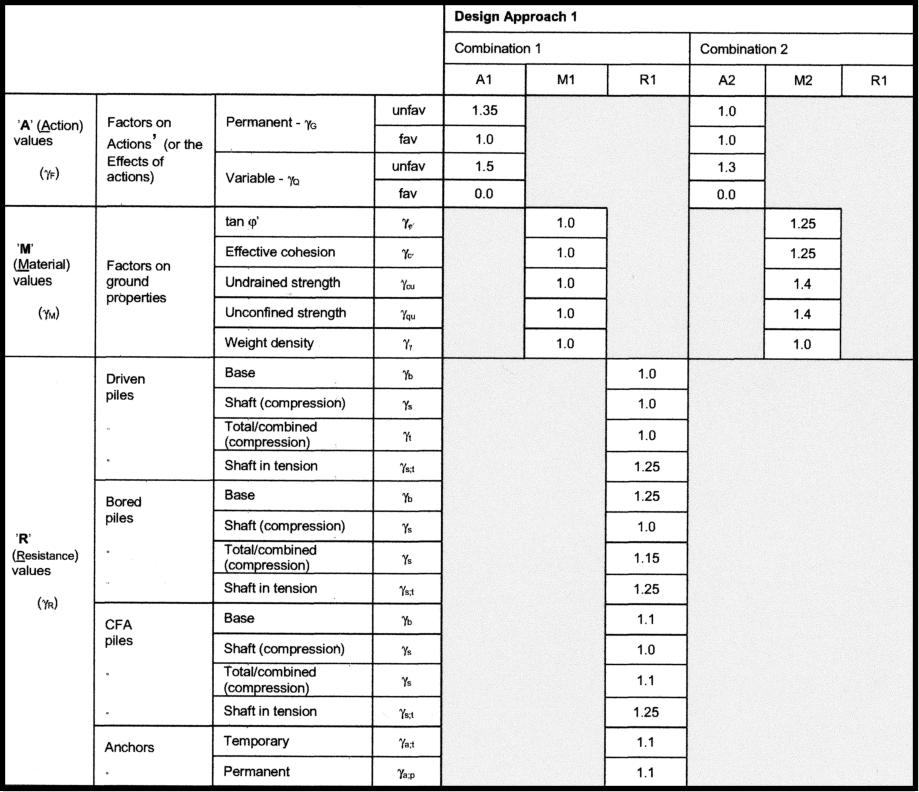
The combination of partial factors relevant to the structural design is provided in combination 1 and
combination 2 as tabled below . The partial factors related to the geotechnic design is also shown. .
Actions
Actions may be forces ( loads applied to the structure or to the ground ) and
displacements ( or accelerations ) that are imposed by the ground on the
structure, or by the structure on the ground. Actions may be permanent e.g.
self-weight of structures or ground , variable e.g. imposed loads on building
floors, or accidental (e.g. impact loads).
Design values of actions ( F d ) are calculated using the general equation:
F d = γ F. F rep
where
F rep is the representative ( or characteristic F k ) value of an action (or of
the effect of an action);
F rep = ψ. F k
γ F is the partial factor for an action (or γ E , for the effect of an action).
The equation for the effect of actions should be

The general equation for the effect of actions should be

The part of the equation inside the brackets represent to combination of permanent and variable actions
In BS EN 1990 one of a number of equations for load
combinations is equation 6,10

Note: The prestress term (γPP ) only applies to prestressed concrete applications
This is a quick, but conservative, method when compared to the alternative equations (6.10a and 6.10b)which are a little more complicated.
6.10b is generally the governing equation in the UK
Properties
Ground properties must be obtained from the results of tests or from other
relevant data such as the back-analysis of settlement measurements or of
failures of foundations or slopes..
Design values of ground properties shall calculated using
X d = X k / γM
where
X k = the characteristic value of a material (ground) property
γ M = the partial factor for the material property.
Design Resistance
The general equation for the resistance of the foundation / structure material

where
γRd = the partial factor for the resistance model uncertainty + geometric deviations.
Xd,i = design value of material property
ad = the design value of a geometric property e.g depth.
This can be simplified to

where
γM,i = γRd .γm,i
.
Design Approach Scenarious applicable to Geotechnic Design
Note: Limited to STR and GEO ULS
There are two sets of combinations to use for the STR and GEO
ultimate limit states. The values for the partial factors to be applied to the actions
for these combinations and the partial factors for the geotechnical
material properties are given in the tables below. Combination 1
will generally govern the structural resistance, and
combination 2 will generally govern the sizing of the
foundations. The partial factors for soil resistance to
sliding and bearing should be taken as 1.0 for both
combinations .
Structural design
| Persistent and transient design situations | permanent actions |
Leading variable actions | Accompanying variable actions |
| Unfavourable |
favourable | Main (if any |
Others |
| Combination 1 Application of combination 1(BS 1997) to set B (BS 1990)
| | Combination of permanent and variable action |
| BS EN 1990(eq 6.10) |
1,35Gk |
1,0Gk |
1,5Qk.1 |
- | 1,5 ψ0.1 Qk.1 |
| BS EN 1990(eq 6.10a) |
1,35Gk |
1,0Gk |
- |
1,5 ψ0.1 Qk.1 |
1,5 ψ0.1 Qk.1 |
| BS EN 1990(eq 6.10b) |
1,35.Gk |
1,0Gk |
0,925.1,5.Qk.1 |
- |
1,5 ψ0.1 Qk.1 |
| Combination 2 Application of combination 2(BS 1997) to set C (BS 1990)
| | BS EN 1990(eq 6.10) |
1,0.Gk |
1,0.Gk |
1,3Qk.1 |
- |
1,3 ψ0.1 Qk.1 |
Geotechnic design
| - | Angle of Shearing
resistance |
effective cohesion | Undrained shear |
Unconfined strength | Bulk density |
| Symbol | γφ |
γc' | γcu |
γqu | γγ |
| Combination 1 | 1,0 |
1,0 | 1,0 |
1,0 | 1,0 |
| Combination 2 | 1,25 |
1,25 | 1,4 |
1,4 | 1,4 |
The Eurocode standard generally requires completion of two calculations for a given foundation providing a check. e.g
calculation to Design Approach 1 combination 2 and Design Approach 1 combination 1 are completed. These are essentially the same
calulations using different partial margins. The first to satify the requiremt for (GEO -ULS) and the second
to satisfy the requirement of (STR ULS). A simple example is shown below using the analylitical method and based on formula found in Appendix D of BS EN1997-1
Simple example
Consider a 2m x 2m concrete pad supporting a column withstanding a permanent vertical load of 1000 kN and an imposed
variable load of 180 kN. The dimensions of the column are ignored for simplicity.

Two calculations sets are completed for this shallow foundation:
1) In accordance with BS EN 1997 Design Approach 1 , Combination 2
The permanent load resulting from the pad and foundation over the pad
Gpad,k= (A).(Depth).(γkt) + (A)..(γsat).(Cover)
Gpad,k= (16).(0,6).(25) + (16).(0,6).(18) = 412,8 kN
The permanent load through the column = Pk = 1000kN
The variable load through the column = Qk = 180kN
The design value of the vertical loads =
Vd = γG ( Gpad,k + Pk ) + γG ( Qk )
Vd = 1,0 . ( 412,8 + 1000) + 1,3 . (180) =1 412,8 + 234 = 1646,8 kN
The design value of the Resistance Rd is given by BS EN 1997 Annex D equation D.1
Rd / A� = (π + 2) c u,d b c s c i c + q d
where
cu,d = cu,k /γcu
cu,d = 30 / 1.4 = 21.4 kPa,
bc = 1(horizontal surface),
ic = 1 (loads purely vertical)
sc = 1 ,2 for square pad
qd = 18. (0.6 + 0.6) = 21,6 kPa = overburden pressure at base of pad.
A' = A = 16m2 ( no loading eccentricity, no bending moments)
Rd = [(3,14 + 2) �.( 21,4 ). ( 1 ). ( 1,2 ) .( 1) + 21,6 ] . 16 = 2124,7 (kN)
VD < RD Therefore design is OK to ULS
2) In accordance with BS EN 1997 Design Approach 1 , Combination 1
The permanent load resulting from the pad and foundation over the pad
Gpad,k= (16).(0,6).(25) + (16).(0,6).(18) = 412,8 kN
The permanent load through the column = Pk = 1000kN
The variable load through the column = Qk = 180kN
Vd = γG ( Gpad,k + Pk ) + γG ( Qk )
Vd = 1.35 (412,8 +1000) + 1.5 (180) = �1907,3 + 270 = 2177,3 (kN)
Rd / A� = (π + 2) c u,d b c s c i c + q d
where
cu,d = cu,k /γcu
cu,d = 30 / 1.0 = 30 kPa
bc = 1(horizontal surface),
ic = 1 (loads purely vertical)
sc = 1 ,2 for square pad
qd = 18. (0.6 + 0.6) = 21,6 kPa = overburden pressure at base of pad.
A�f = A = 4m2 ( no loading eccentricity, no bending moments)
Rd = [(3,14 + 2) �.(30,0 ). ( 1 ). ( 1,2 ) .( 1) + 21,6 ] . 16 = 3307 (kN)
VD < RD Therefore design is OK to ULS
Site Investigations
Prior to inititation of detailed foundation design. Site Investigations should be completed and a geotechnical
report should be completed in accordance with BS EN 1997-2 Eurocode 7:Geotechnical design- Part 2 :Ground investigation and testing.
In order to allow the investigation to commence it is necessary to know the general form, size and loading related
to the construction and the location of the structure on the site. The aims of the geotechnical investigation are to estabish the soil rock and
groundwater conditions and to determine the properties of the soil and rock, and to gather additional relevant information about the site.
The use of in-situ tests and off site laboratory tests are available to obtain the necessary rock and soil properties. Various in-situ test procedures are available for obtaining the properties
of the rock or soil. Details of the test equipment and the relevant methods of completing the tests are provided in the noted standard.
The main tests and short descriptive notes are provided below.
Tests Used for site investigations.
1) Cone Penetrations Test (CPT)
This test is used to determine the resistance of soil and soft rock to the penetration of a cone and the local friction on
a sleeve. The CPT consists of pushing a cone penetrometer vertically into the soil using a series of push rods.
The cone penetrator shall be pushed into the soil at a constant rate (controlled between 1,5 -2,5 cm/s ). The penetrometer
comprises the cone and, if appropriate, a cylinderical shaft or friction sleeve. The cone tipe shall have a diameter of either
3,6 or 4,4 cm. The penetration resistance of the cone ( qc ) as well as, if appropriate the local friction
on the friction sleeve shall be measured. An advantage of CPT over the Standard Penetration Test (SPT) is a more
continuous profile of soil parameters, with CPTU data recorded typically at 2 cm intervals.
2) Pressuremeter Test (PMT)
The pressuremeter test is an in-situ testing method which is commonly used to achieve a quick and easy measure of
the in-situ stress-strain relationship of the soil which provides parameters such as the elastic modulus.
This tests measures in-situ deformation of soil and soft rock caused by the expansion of a cylinderical flexible membrane
under pressure. The test involves inserting a probe containing a cylinderical flexible membrane into the
ground either in a pre-formed borehole, or by self-boring or by full displacement pushing.
When at a predetermined depth the membrane is expanded under pressure and readings
of pressure and expansion are recorded until a maximum expansion for the particular device is reached.
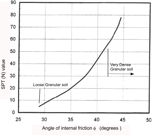
3) Standard Penetration Test (SPT)
This test is to provide an indication of the relative density of granular deposits,
such as sands and gravels from which it is virtually impossible to obtain undisturbed samples. The benefit of the test, and
the main reason for its widespread use is that it is simple and inexpensive.
These tests determine the resistance of soil at the base of a borehole to dynamic penetration of a
split barrel sampler (or solid cone) and obtaining of disturbed samples for identification purposes.
The sampler is driven into the soil by dropping a hammer 63,5 kg mass onto an avil or drive head from a height of 760mm. the
number of blows (N) necessary to achieve a penetration of the sampler of 300mm ( after its penetration under gravity and below a seating drive )
is the penetration resistance.
The test uses a thick-walled sample tube, with an outside diameter of 50 mm and an inside diameter of 35 mm, and a length of around 650 mm.
This is driven into the ground at the bottom of a borehole by blows from a slide hammer. The sample tube is
driven 150 mm into the ground and then the number of blows needed for the tube to penetrate each 150 mm up to a depth of 450 mm is recorded.
The sum of the number of blows required for the second and third 150 mm. of penetration is termed the "standard penetration resistance" or
the "N-value". In cases where 50 blows are insufficient to advance it through a 150 mm interval the penetration after 50
blows is recorded. The blow count provides an indication of the density of the ground, and it is used in many empirical
geotechnical engineering formulae.
4) Flexible Dilatometer Test(FDT)..Using a cylinderical borehole dilatometer probe.
This test determines the deformability of rock (rock-dilatometer test, RDT) and soil (soil dilatometer test SDT) from
measurements of the radial expansion of a boreholes section under a known radial pressure applied by means of a
cylinderical dilatometer probe. The test consists of inserting a cylinderical probe,
having an outer flexible membrane into a borehole and measuring at selected intervals, or in a semi-continuous manner,
the radial displacement of the borehole while inflating the probe under known radial pressure.
Bearing Values
Presumed bearing values acceptable for category 1 structures and preliminary calcs for category 2
| Category | Type of soil |
Presumed allowable
bearing value ( kN/m2 ) |
Non- cohesive soils
Note:Width of foundation >1m | Dense gravel , or dense sand and gravel |
>600 |
| Medium dense gravel or med.dense sand and gravel |
<200 to 600 |
| Loose gravel or loose sand and gravel |
< 200 |
| Compact sand |
> 300 |
| Medium dense sand |
100 - 300 |
| loose sand |
< 100 |
Cohesive soils
Note: subject to long term consolidation | Very stiff boulder clay and hard clay |
300 - 600 |
| Medium dense gravel or med.dense sand and gravel |
<200 to 600 |
| Stiff clay |
150 - 300 |
| Firm clay |
75- 150 |
| Soft clay and silt |
< 75 |
| Very soft clay and silt |
Not applicable |
Basic soil elements
Sand
Cohesionless granules formed mainly from hard particles . In bulk it is very permeable owing to the voids.
Primary characteristic, frictional resistance to shearing forces . Often found mixed with gravel.
Gravel
Similar to sand but comprised of larger particles of solid stone
Clay
Properties depend mainly on the consistency , the water content being the most important. Highly cohesive, has a definite
mobility and yields under pressure when the moisture content exceeds 20%. Yielding takes place by expulsion
of the water from the pores. Therefore the rate at which compression occurs is slow owing to the low
permeability. Often mixed , or stratified with sand. Pure clays have a very a very small angle
of internal friction which approach zero in soft clays and especially soft puddled clays.
Silt
Similar to course clay , fine grained micaceous silts can be mistaken for clay, although unsatisfactory for
load-bearing because disturbance of ground water may completely alter the nature of the material.
Organic silts containing vegetable matter are highly compressible and not suitable for load bearing.
Types of Soils
The classification of soils relevant to the construction of foundations and earthworks it different to the geological classification.
In engineering a classification based on physical characteristics is adopted.
| Sieve Size | Description |
| mm |
| 0,002-0,06 | Silt |
| 0,06-2 | Sand |
| 2-60 | Gravel |
| 60-200 | Cobbles |
| over 200 | Boulders |
In reality soils are non uniform but are mixed and general descriptions as shown below apply
| Mix | Description |
| Slightly sandy GRAVEL | <5% Sand |
| Very sandy GRAVEL | 20%-50% Sand |
| Very gravelly SAND | 20% to 50% gravel |
| Slightly Silty GRAVEL/SAND | up to 5% silt |
| Very silty GRAVEL/SAND | 15% to 35% silt |
| Clayey GRAVEL/SAND | 5% to 15% silt |
| Sandy SILT/CLAY | 35% to 65% sand |
| Very coarse | over 50% cobbles/boulders |
| Sandy GRAVEL | 5%-20% Sand |
| Gravel/SAND | equal proportions |
| Slightly gravelly SAND | up to 5% gravel |
| Silty SAND/GRAVEL | 5% to 15% silt |
| Slightly clayey SAND/GRAVEL | up to 5% clay |
| Very clayey SAND/GRAVEL | 15% to 35%clay |
| Gravelly SILT/CLAY | 35% to 65% gravel |
Soil Properties
Note:symbols not in line with BS EN 1997
The behaviour of a soil is dependent on the water content which is important in the choice of shear
strength parameters including the internal angle of shear φ and the cohesion c.
If water is present the applied loads are supported by the pore water pressures. For granular soils above the
water table, pore water pressures dissipate almost immediately as the water drains away and loads are effectively
carried by the soil structure. For fine grained soils, which are not as free draining pore water pressures
take much loinger to dissipate. Water and pore water pressures affect the strength and settlement
characteristics of soil.
In carrying out geotechnical design assessments it is necessary to distinguish between drained and undrained
conditions ( short and long term conditions ). Short term design relates to the pore water pressures and the design must be carried
out on the basis of φu and cu. for the drained ( long term conditions ) when the pore water
pressure has been dissipated the design should be based on φ' and c '
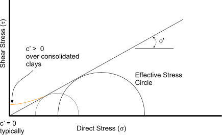
In terms of effective stresses, the drained shear strength is often approximated by:
τ = σ' tan(φ') + c'
Where σ' =( σ - u), is defined as the effective stress. σ is the total stress applied normal to the shear plane,
and u is the pore water pressure acting on the same plane.
φ' = the effective stress friction angle, or the "angle of internal friction" after Coulomb friction.
The coefficient of friction μ is equal to tan(φ'). Different values of friction angle can be defined,
including the peak friction angle, φ'p, the
critical state friction angle, φ'cv, or
residual friction angle, φ'r.
c' = is called cohesion, however, it usually arises as a consequence of forcing a straight line to fit through measured
values of (τ,σ') even though the data actually falls on a curve. The intercept of the straight line on the shear stress
axis is called the cohesion. The resulting intercept depends on the
range of stresses considered: it is not a fundamental soil property. The non linearity of the failure
envelope occurs as a result of the close packing of the soil particles which depends on the confining pressure.
Properties of Sand
| Density | Angle of Internal Friction | Apparent cohesion (Undrained) | Safe Bearing Pressure |
| kg/m3 | degrees | kN/m2 | kN/m2 |
Before excavation
Dry =1 450
Dry fine =1 600
Wet =1 850
Very Wet =1 925 |
Moist (Drained)
Loose
Fine or silty =1 600-1 775
Coarse of Medium=1 900-2 100
Compact
fine or silty=1 750-2 175
Coarse of medium=1 675-1 925 |
Compact
well graded =40-50
Medium fine or silty =35-40
Loose
Well graded =35-40
Uniform coarse
medium, fine or silty =30-35
Fine dry=30-35
|
Nil |
Compact
Well graded = 400-600
Uniform= 200-400
Loose
Well graded = 200-400
Uniform = 100-200 |
Properties of Gravel
| Density | Angle of Internal Friction | Apparent cohesion (Undrained) | Safe Bearing Pressure |
| kg/m3 | degrees | kN/m2 | kN/m2 |
Common = 1 775
River Gravel =2 250
Loose shingle =1 850
Sandy =1 925 |
1600 -2 000
-
-
- |
Common = 35 - 45
Shingle = 40
Sandy
compact = 40 -45
Loose = 35 - 40
|
Nil |
Compact = 400 - 700
Loose = 200 - 400
Sandy
compact = 400 - 600
Loose = 200-400 |
Properties of Rock
| Density | Safe Bearing Pressure |
| kg/m3 | kN/m2 |
Grey Chalk = 2 400
Sandstone =2 200 - 2800
Shale =2 400 - 2800
Limestone = 2 300 - 2700
Shale = 2 575
Gneiss =2 600-2900 |
Granite =2 600-2 700
Chalk hard block = 80-600
Strong Shales and Mudstones = 2000
Schists/Slates = 3000
Strong limestones and hard sandstones = 4000
Strong igneous rock and Gneises = 10 000 |
Properties of Filling
| Density | Angle of Internal Friction | Apparent cohesion (Undrained) | Safe Bearing Pressure |
| kg/m3 | degrees | kN/m2 | kN/m2 |
Crushed Rock
Granite = 1 600 - 2 100
Basalts dolerites = 1 775 - 2 250
Limestone, sandstone = 1 275 -1 925
Broken Chalk = 95 - 1300
Broken shale = 1 600 - 2 100
Broken brick = 1 125 - 1 775
Ashes 640 - 975 |
Crushed Rock =35 - 45
Broken Chalk = 35 -45
Broken Shale = 30 -45
Broken brick = 35 -45
Ashes 35 -45 |
- |
Depends on degree of
consolidation and should
be determined by test |
Properties of Clay
| Density | Angle of Internal Friction | Apparent cohesion (Undrained) | Safe Bearing Pressure |
| kg/m3 | degrees | kN/m2 | kN/m2 |
Dry = 1 775
Damp (drained)= 1,850
Wet = 1 975
Sandy loam = 1 600
Marl = 1 775
Gravelly clay = 2,000 |
Saturated
Very stiff boulder hard shale clay
Stiff= 1 925-2 2250
Firm = 1,750-2 100
Soft = 1 600 -1925 |
Low or zero in undrained condition |
Hard = 250
very stiff = 150-200
Stiff = 15-150
Firm = 37- 75
Soft= 18-37
Very soft < 18 |
Hard = 550
very stiff = 330 -550
Stiff = 170 - 330
Firm = 85 - 170
Soft 40 - 85
Very soft < 40 |
Fill, and Ground improvement
Sometimes it is necessary to acheive adequate ground conditions by
-Placing naturual soil, crushed rock, stone fragments or suitable waste producs,
- dewatering.
- treating the ground
-reinforcing the ground.
These actions may be completed beneath foundations , as backfill to excavations and retaining structures, as general
landfill or as embankments for infrastructure.
The materials and methods should be selected such that the resulting ground system is suitable for design function over the design
life of the construction.
Fill and backfill beneath and around foundations should be compacted so that there is no possibility of subsidence.
Types of Foundations
There are two primary types of foundations shallow foundations as used for houses and smaller commercial properties and deep foundations
as used for multi story buildings
Shallow Foundations-general notes and information
Shallow foundations, often called footings, are usually embedded about a meter or so into soil. One common type is the spread footing which
consists of strips or pads of concrete (or other materials) which extend below the frost line and transfer the weight from walls and columns
to the soil or bedrock. The naming conventions for different types of footings vary between
different engineers.
Pad foundations are used to support individual or multiple columns, spreading the load to the ground below.
They are generally square or rectangular in plan, with the plan area being determined by the permissible bearing pressure of the soil.
The shape in plan will be dictated by the arrangement of the columns and the load to be transferred into the soil. The thickness of
the pad must be sufficient to ensure distribution of the load. In general some reinforcement (either welded steel fabric or reinforcing bars,
depending on the loads involved) may be required.
Strip foundations are used to support walls or closely spaced rows of columns.
Strip foundations under walls , particularly domestic walls can be form 1:3:6 concrete of a thickness not less than the projection beyond the
wall facing but not less than 150 mm.
Suggested strip foundation widths
are provided in table below.
| Type of subsoil |
condition | Minimum width in mm for total load in kN/linear m of not more than |
| 16 500 kN/m | 25 000 kN/m | 33 000 kN/m |
41 500 kN/m | 50 000 kN/m | 58 000 kN/m |
66 000 kg/m |
Gravel
Sand
Clay
Sandy/Clay | Compact
Stiff | 230 | 230 | 300 | 380 | 460 | 530 | 600 |
Clay
Sandy Clay | Firm | 230 | 300 | 380 | 460 | 570 | 690 | 760 |
Sandy
Silty Sand
Clayey Sand | Loose | 300 | 460 | 600 | - | - | - | - |
Silt
Clay
Sandy Clay
Silty Sand | Soft | 340 | 530 | 690 | - | - | - | - |
Silt
Clay
Sandy Clay
Silty Sand | Very Soft | 460 | 690 | 900 | - | - | - | - |
Another common type of shallow foundation is the slab-on-grade foundation where the weight of the building is
transferred to the soil through a concrete slab placed at the surface. Slab-on-grade foundations can be reinforced mat
slabs, which range from 25 cm to several meters thick, depending on the size of the building, or post-tensioned slabs,
which are typically at least 20 cm for houses, and thicker for heavier structures.
Shallow Foundations / Spread Foundations- Notes relevant to design to Eurocodes
The geotechnical design of spread foundations (e.g. strip and pad foundations) is covered by
section 6 of Eurocode 7, Part 1 and this gives three methods for design:
.. Direct method. - Calculations are carried out for each limit state.
.. Indirect method . - Experience and testing used to determine serviceability limit state parameters that also
satisfy all relevant limit states.
...Prescriptive method. - Involves the use of presumed bearing resistance.
For most spread foundations, settlement will be the governing criterion; traditionally �allowable bearing
pressures have been used to limit settlement. The increasing the factor of safety on bearing resistances
to control settlement may still be used with the prescriptive method except for soft clays where Eurocode 7
requires settlement calculations to be completed.
The prescriptive method may be used where calculation of the soil properties is not possible or necessary and
can be used provided that conservative rules of design are used. A member country may currently
determine presumed (allowable) bearing pressures and these values may continue be used for category 1 structures and
preliminary calculations for category 2 structures . (refer to table above showing presumed bearing values ) .
Alternatively, the presumed bearing resistance to allow for settlement can be determined by the specialist
engineer and included in the geotechnical design report.
Approximate quick design method for shallow foundations
A general equation of allowable bearing capacities is based on work be Terzaghi is shown below
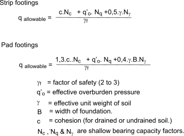
Table of factors
Internal angle of shear
φ | Bearing capacity factors |
| Nc | Nq | Nγ |
| 0 | 5,0 | 1,0 | 0,0 |
| 5 | 6,5 | 1,5 | 0,0 |
| 10 | 8,5 | 2,5 | 0,0 |
| 15 | 11,0 | 4,0 | 1,4 |
| 20 | 15,5 | 6,5 | 3,5 |
| 25 | 21,0 | 10,5 | 8,0 |
| 30 | 30,0 | 18,5 | 17,0 |
| 35 | 45,0 | 34,0 | 40,0 |
| 40 | 75,0 | 65,0 | 98,0 |
Deep foundations -General Notes
A deep foundation is used to transfer a load from a structure through an upper weak layer of soil to
a stronger deeper layer of soil. There are different types of deep footings including impact driven piles, drilled
shafts, caissons, helical piles, and earth stabilized columns. Historically, piles were wood, later steel,
reinforced concrete, and pre-tensioned concrete. The following notes
are provided as background information.
Piling will normally be undertaked under the advice of specialist engineers.
Piling may be the preferred foundation option under the following circumastances:
When the loads transmitted to the ground by the walls or columns of a building or other structure are of such a magnitude
that the use of conventional foundations would result in uneconomically large bases
When the loads cannot be taken on shallow foundations even if the bases occupy the whole of the building area
When the upper strata are very weak or include unstable soils such as peat or unconfined sand the loads may be transferred
through the faulty strata to a firm subsoil capable of supporting the loads,
When the upper strata are subject to large moisture movements piling may be desirable to ensure foundations at a stable level.
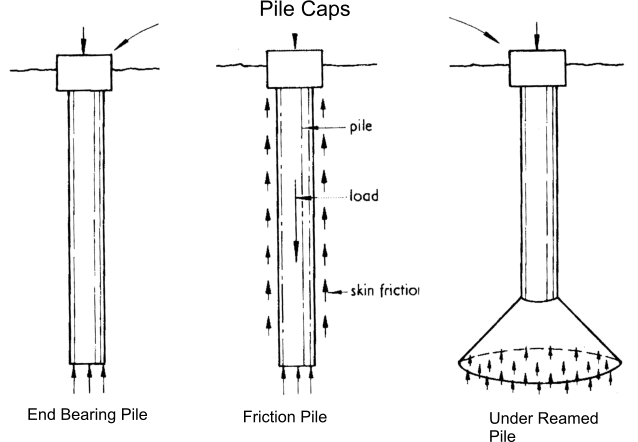
Two basic type of piling design are used: the first is , in effect , a column sunk into the ground whose
base rests upon a suitable bearing such as rock. Some of these types have belled bottoms to increase
the bearing surface : the second type of pile is the friction pile which derives its support from the
friction of the surface of the pile against the surrounding soil. Obviously these piles also tend to gain
support at the bottom bearing surface, but the principlal design basis is frictional resistance to movement.
The physical form of a particular pile depends upon the method of its sinking. Piles can be preformed and
driven into the ground or they can be cast in a formed hole .
Bored Piles- three types..
- A steel tube is dropped into the soils and then withddrawn and the soil retained in the bore is removed. An outer steel
shell is driven down the bore as the work proceeds to prevent wall collapse. When concrete casting takes place the shell is removed in
stages as the. work procedes.
- A rotating drill with shell casing cuts into the soil.
- A large diameter auger cuts broad and short piles
Driven Piles
Two types of driven piles are used :steel piles which are either columns or
formed sheets: concrete piles - usually precast with a steel tip to aid driving.
The sinking of driven piles or sheet piling can be by traditional pile-drivers or ,in some cases,
by high speed vibration . The latter is often used in built-up areas.
Shells on bored piles are often
sunk using the same methods.
Multiple piles
When the load from a building requires more than one pile to provide adequate support , a number of piles are
grouped in a "cluster" under a common pile cap which compensates for errors in positioning of the piles and
also distributes the load evenly across the piles.
Basic calcs for estimates of pile capacities
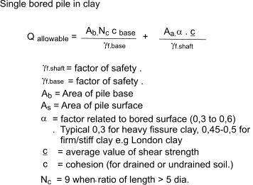
Single bored piles in clay
Groups of piles below pile cap.
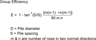
A goup of piles have a much lower overall capacity than the sum of the individual capacities. An estimate of the
efficiency of a group is provided by the following equation
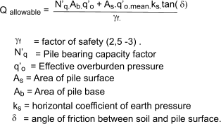
Piles in granular soils
|
Typical values of N'q
Internal angle of shear
φ | Pile Length/ Pile dia |
| 5 | 20 | 70 |
| 25 | 16 | 11 | 7 |
| 30 | 29 | 24 | 20 |
| 35 | 69 | 53 | 45 |
| 40 | 175 | 148 | 130 |
|
Typical values of δ
Pile Face /
Soil type |
Angle of pile friction./angle of soil friction (δ / φ ' ) |
| Smooth coated steel/sand | 0,5-0,9 |
| Rough-corrugated steel/sand | 0,7-0,9 |
| Cast in place concrete/sand | 1,0 |
| Precast concrete /sand | 0,8-1,0 |
| Timber/sand | 0,8-0,9 |
|
Typical values of ks
| Installation-pile type. |
coefficient to hor. soil stress / earth pressure at rest (ks /ko ) |
| Driven piles large displacement | 1,0 - 2,0 |
| Driven piles small displacement | 0,75 - 1,25 |
| Bored cast-in-place piles | 0,7 - 1,0 |
| jetted piles | 0,5 - 0,7 |
|
Pile caps
The construction load is transferred to the pile /piles using concrete platforms called pile caps.
Piles under the pile cap should be laid out symmetrically in both directions.
The column or wall on the pile cap should be centered at the geometric center of the pile cap in
order to transfer the load evenly to each pile. Examples of pile layout pattern are shown below:
In general, piles should be spacing at 3 times of pile diameter in order to transfer load effectively to soil.
If the spacing is less than 3 times the diameter of the pile, pile group settlement and bearing capacity should be checked.
The pile cap thickness is normal determined by shear strength. For smaller pile caps, the thickness is
normally governed by deep beam shear. For large pile caps, the thickness is governed by direct shear.
When necessary, shear reinforcement may be used to reduce the thickness of the pile cap
Table of suggested pile cap thickness to ensure that the critical design is based on sum of pile forces across centre and not
on the punching shear.
| Pile Diameter ( mm ) | 300 | 350 | 400 | 450 | 500 | 550 | 600 |
| Pile cap Depth (mm) | 700 | 800 | 900 | 1000 | 1100 | 1200 | 1400 |

Piles in accordance with Eurocodes
The design of piles is normally completed by specialists engineers and should be based on detailed experience of the
site geology or preferably following extensive site tests. BS EN-1997- specifically indicates that design of piles should be
based on one of the following criteria
- the results of relevant pile load tests ;
- calculations that are based on valid load tests
- the results of dynamic tests ( based on valid load tests)
- observations of the performance of comparable piles.
More notes to follow..
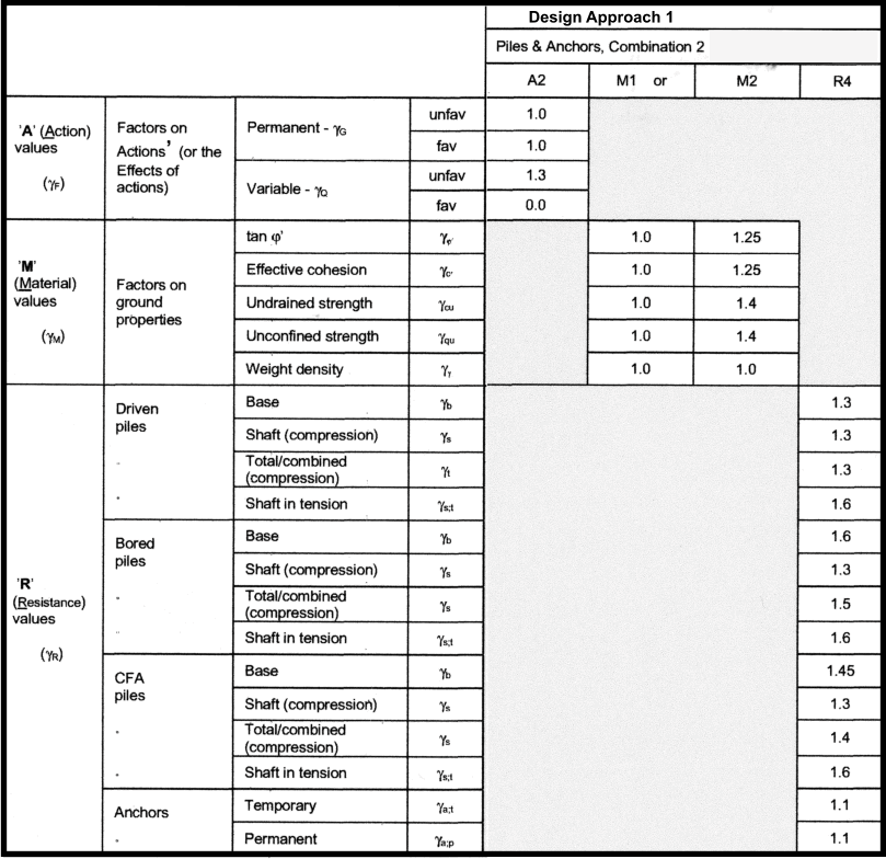
Tables summerising Partial factors
| 


