Introduction
This page includes some notes on the design of masonry walls based on the principles as
specified in BS EN 1996 part 1 2005. The notes allow initial estimates of the design requirements sufficient
for initial studies to be completed . For detail design the relevant standards must be used.
The notes below include a large number of safety margins, design factors and tables and very few actual design equations.
In principle a simple masonry built construction is based on a number of walls supporting floors and roof constructions.
The walls are transferring the structure loads to the foundations and are primarily under compression. Masonry walls
have poor strength is bending shear and torsion. To increase the resistance of the walls to bending, shear and torsion,
support is provided by piers , intersecting walls and intersecting floors. Masonry walls
are also strengthened using reinforcement.
Strictly for each masonry element it is necessary to calculate
Axial loads resulting from vertical and horizontal actions
Shear loads resulting from vertical and/or horizontal actions
Bending moments due to vertical and/or lateral actions
Torsional moments.
For each wall the design strength values for the material shall be obtained by dividing the characteristic values by the
appropriate safety margin γ m. These design value shall be used to obtain the Ultimate Limit design
and serviceability limit for the building elements for operation and serviceability.
The design should ensure that under all operating conditions the
stress conditions cannot exceed the Ultimate limit and Serviceability limit .
Relevant Standards
BS EN 1996-1-2 : 2005 .. Eurocode 6. Design of masonry structures. General rules. Structural fire design
and structures..
BS EN 1996-2 : 2006... Eurocode 6. Design of masonry structures. Design considerations, selection of materials and execution of masonry
BS EN 1996-3 : 2006... Eurocode 6. Design of masonry structures. Simplified calculation methods for unreinforced masonry structures
Symbols
t = Actual wall thickness (mm)
t 1= Actual wall thickness one leaf of cavity wall (mm)
t 2= Actual wall thickness second leaf of cavity wall (mm)
tef = Effective wall thickness (mm)
A' s = Area of Compression reinforcement
b = width or effective width of section
b w = average width of web.
α =the bending moment coefficient.
μ = the orthogonal ratio;
γ f = Partial safety factor for load
γ m = Partial safety factor for material strength
σd = design compressive stresses
E n = Characteristic Earth Load
G k = Characteristic dead Load
Q k = Characteristic imposed Load
W k = Characteristic Wind Load
f b = Normalised compressive strength of masonry units
f k = Characteristic strength of masonry
f m = Compressive strength of mortar
fd = design compressive strength of masonry
f cu = Characteristic strength of concrete
f y = Characteristic strength of reinforcement
Wk =is the characteristic wind load per unit area.
|
Category of masonry units
The design shall include the categorisation of the masonry units into category I or category II.
A category I unit is a higher quality unit with guaranteed properties defined BS EN 771 1-6, and requires third party certification and
monitoring of the production control system. A category II unit is simply one that is not a category I grade.
Grouping of masonry units
The relevant standard includes a table grouping masonry units on the basis of volumes of
holes as a percentage of the gross volume and the thickness of the webs and shells.
There are four groups . Group 1 has the lowest % of holes and lowest shell/web thickness
and group 4 the highest. Information on the group 1 values are provided below
Group 1
Volume of all holes =< 25%
Volume of any hole =< 12,5%
Value of thickness of webs/shells (mm) no requirement
Value of thickness of webs/shells (% of o/all thickness) -no requirement
Group 2
| Criteria | Clay | Calcium Silicate | Concrete |
Volume of all holes (%of gross) | > 25:=< 55 | > 25:=< 55 | > 25:=< 60 |
Volume of any hole (%of gross) | Each of multiple holes = < 2
grip holes up to a total of 12,5 | Each of multiple holes = < 15
grip holes up to a total of 30 | Each of multiple holes = < 30
grip holes up to a total of 30 |
Declared value of thickness of webs and shells (mm) | web >= 5
shell > = 8 | web >= 5
shell > = 10 | web >=15
shell > = 18 |
Declared value of combined thickness of webs and shells (% of overall width) | > = 16 | > = 20 | > = 18 |
Group 3
| Criteria | Clay | Calcium Silicate | Concrete |
Volume of all holes (%of gross) | > 25:=< 70 | not used | > 25:=< 70 |
Volume of any hole (%of gross) | Each of multiple holes = < 2
grip holes up to a total of 12,5 |
not used | Each of multiple holes = < 30
grip holes up to a total of 30 |
Declared value of thickness of webs and shells (mm) | web >= 3
shell > = 6 |
not used |
web >=15
shell > = 15 |
Declared value of combined thickness of webs and shells (% of overall width) | > = 12 |
> Not used | > = 15 |
Group 4
| Criteria | Clay | Calcium Silicate | Concrete |
Volume of all holes (%of gross) | > 25:=< 70 | not used | > 25:=< 50 |
Volume of any hole (%of gross) | Each of multiple holes = < 30 |
not used | Each of multiple holes = < 25 |
Declared value of thickness of webs and shells (mm) | web >= 5
shell > = 6 |
not used |
web >=20
shell > = 20 |
Declared value of combined thickness of webs and shells (% of overall width) | > = 12 |
> Not used | > = 45 |
Notes:
1. Holes may consist of formed vertical holes through the unit or frogs or recesses.
2. If there is national experience, based on tests, that confirms that the safety of the masonry is not
reduced unacceptably when a higher proportion of holes is incorporated, the limit of 55% for clay units
and 60% for concrete aggregate units may be increased for masonry units that are used in the country with national experience.
3.The combined thickness is the thickness of webs and shells, measured horizontally across the unit at right angles to the face of the wall
Characteristic strength of masonry
When test data for obtaining the characteristic strength fk is not available,
then the approximate characteristic strength of plain masonry made with general
purpose mortar may be calculated using the equation
fk = K *( fb 0.70 )*( f m0.30 ) [MPa]
when f m less than 20 MPa or 2.f b, whichever is the smaller and f b is less than
75 MPa
The value of constant K depends on the classification of masonry units into groups. Following is a basic list
providing a extract of table in the relevant standard listing K values against mortar type and masonry group.
The list below simply provides the values of K related to group 1 and for general purpose mortar.
Clay bricks 1 K = 0,55
Calcium Silicate bricks K =0,55
Aggregate concrete blocks K = 0,55
Autoclaved Aerated concrete K= 0,55
Manufactured stone K= 0,45
Dimensioned natural stone K= 0,45
Note: The equations above provide an edited extract of the range of groups and relationships listed in
the relevant code BS EN 1996. For other grades of mortar the indices in the equation are different
Table of characteristic compressive strength of masonry, fk, in N/mm2
| Constructed with standard format bricks of clay and calcium silicate having no more
than 25% of formed voids, or 20% frogs |
Mortar strength
Class/Designation |
Compressive strength of unit (N/mm2) |
| 5 | 10 | 15 | 20 |
30 | 40 | 50 | 75 |
100 | 125 | 150 |
| M12 / (i) | 2.5 | 4.0 | 5.3 | 6.4 | 8.3 | 10.0 | 11.6 |
15.2 | 18.3 | 21.2 | 23.9 |
| M6 / (ii) | 2.5 | 3.8 | 4.8 | 5.6 | 7.1 | 8.4 | 9.5 | 12.0 |
14.2 | 16.1 | 17.9 |
| M4 / (iii) | 2.5 | 3.4 | 4.3 | 5.0 | 6.3 | 7.4 | 8.4 |
10.5 | 12.3 | 14.0 | 15.4 |
| M2 / (iv) | 2.2 | 2.8 | 3.6 | 4.1 | 5.1 | 6.1 | 7.1 |
9.0 | 10.5 | 11.6 | 12.7 |
Modulus of Elasticity of masonry
The short term modulus of elasticity E, is properly obtained my tests in
accordance with the relevant code BS EN 1052-1.
In absence of this information E can be taken as 1000. fk unless the local national
codes provides other recommendations. The long term E value
is affected by creep such that Elt = E / (1+ φinf ).
φinf being the creep coefficient (This can vary from 0,5 to 2 ).
Partial Safety margins related to Ultimate limit state design
When using the design relationship for the ultimate limit the design load is taken as
the sum of the products of the component characteristic loads multiplied by the
most severe of the relevant partial safety factor.
1) Dead and imposed load
Design dead load = 0.9 Gk or 1.4 Gk
Design imposed load = 1.6 Qk
Design worst credible earth and water lateral load = 1.2 Eu
2) Dead and wind load
Design dead load = = 0.9 Gk or 1.4 Gk
Design wind load = 1.4 Wk
Design worst credible earth and water lateral load = 1.2 Eu
If a wall is free standing and laterally loaded wall panels which are not relevant to the safety of the remaining structure
the design case wind load may be taken as 1,2 Wk
3) Dead, imposed and wind load
iii) Design dead load = 1.2 Gk
iii) Design imposed load = 1.2 Qk
iii) Design wind load = 1.2 Wk
iv) Design worst credible earth and water lateral load = 1.2 Eu
|
Normalised mean compressive strength of masonry unit fb, in N/mm2
The mean value determined by testing of at least ten equivalent, air dried, 100 mm by 100 mm specimens cut from the masonry unit.
In the case where the strength is obtained by testing full sized units, the mean value of strength is multiplied by the shape factor d, which
takes into account the actual dimensions of the unit. In case the compressive strength of masonry is specified as characteristic strength, it should
be first converted to the mean equivalent using a conversion factor based on the coefficient of variation, and than multiplied by the shape
factor d.
In the relevant European standards (BS EN 771-1-6) are given minimum value of normalised mean compressive strength of masonry units
to be used for masonry walls:
Clay units: min fb =2.5 MPa
Calcium silicate units: min fb =5.0 MPa
Concrete units: min fb=1.8 MPa
Autoclaved aerated concrete units: min fb=1.8 MPa
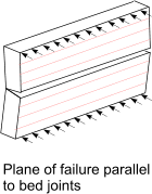
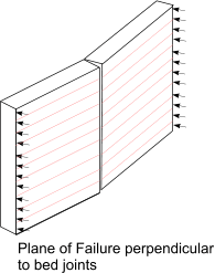
Characteristic flexural strength of masonry, fkx, in N/mm2
Based on BS EN 1996
| |
 |
 |
Masonry Unit |
Failure plane parallel to bed |
Failure plane perpendicular to bed |
Gen Pur Mortar
fm < 5N/mm 2 |
Gen Pur Mortar
fm >= 5N/mm 2< |
Thin Layer mortar |
Lightweight mortar |
Gen Pur Mortar
fm < 5N/mm 2 |
Gen Pur Mortar
fm >= 5N/mm 2< |
Thin Layer mortar |
Lightweight mortar |
| fxk1 N/mm2 | fxk2 N/mm2 |
| Clay | 0,1 | 0,1 | 0,15 | 0,10 | 0,2 | 0,40 | 0,15 | 0,10 |
| Calcium Silicate | 0,05 | 0,1 | 0,2 | not used | 0,20 | 0,40 | 0,30 | not used |
| Aggregate concrete | 0,05 | 0,1 | 0,2 | not used | 0,20 | 0,40 | 0,30 | not used |
| Autoclaved Aerated concrete den <400 kg/mm2 | 0,05 | 0,1 | 0,15 | 0,10 | 0,20 | 0,20 | 0,20 | 0,15 |
| Autoclaved Aerated concrete den >= 400 kg/mm2 | 0,05 | 0,1 | 0,15 | 0,10 | 0,20 | 0,40 | 0,30 | 0,15 |
| Manufactured stone | 0,05 | 0,1 | not used | not used | 0,20 | 0,40 | not used | not used |
| Dimension Natural stone | 0,05 | 0,1 | 0,15 | not used | 0,20 | 0,40 | 0,15 | not used |
Characteristic initial shear strength , fvko, in N/mm2
Based on BS EN 1926
| Masonry unit | fvko |
| General Purpose Mortar of strength class given |
Thin Layer mortar | Lightweight mortar |
| Clay Mortar class M10-M20 | 0,3 | 0,3 | 0,15 |
| Clay Mortar class M2,5-M9 | 0,2 | 0,3 | 0,15 |
| Clay Mortar class M1,5-M1 | 0,1 | 0,3 | 0,15 |
| Calcium silicate Mortar class M10-M20 | 0,2 | 0,4 | 0,15 |
| Calcium silicate Mortar class M2,5-M9 | 0,15 | 0,4 | 0,15 |
| Calcium silicate Mortar class M1,5-M1 | 0,1 | 0,4 | 0,15 |
| Aggregate concrete blocks | 0,20 | 0,3 | 0,15 |
| Autoclaved Aerated concrete | 0,15 | 0,3 | 0,15 |
Manufactured stone
and dimensioned natural stone | 0,1 | 0,3 | 0,15 |
Characteristic shear strength of masonry
The characteristic shear strength of masonry fvk is determined for tests. However it
is allowable to use the following equation if the mortar is general purpose mortar or designated thin layer mortar.
fvk = fvko +0,4.σd
Partial safety margins for materials
The design value of a material is simply obtained by dividing its characteristic value by the relevant partial factor for the material. The
partial safety margin for the compressive strength of masonry construction (general) (γ mc ) is taken as 3,5 and the partial safety margin
for the flexural strength of masonry (γ mf ) is 3,0 ( From BS 5628). These margins are based on normal methods of construction.
table showing values of γM (From BS EN 1996)
| Material |
γ M |
Class |
| 1 | 2 | 3 | 4 | 5 |
| Masonry units of cat I,designed mortar | 1,5 | 1,7 | 2,0 | 2,2 | 2,5 |
| Masonry units of cat I,prescribed mortar | 1,7 | 2,0 | 2,2 | 2,5 | 2,7 |
| Masonry units of cat II, any mortar | 2,0 | 2,2 | 2,5 | 2,7 | 3,0 |
| Anchorage of reinforcing steel | 1,7 | 2,0 | 2,2 | 2,5 | 2,7 |
| Reinforcement steel and prestressing steel | 1,15 |
| Ancillary components | 1,7 | 2,0 | 2,2 | 2,5 | 2,7 |
| Lintels | 1,5 to 2,5 |
Preliminary sizing of masonry walls.
Effective height
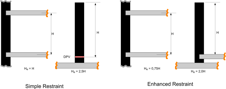
The effective height of a load bearing wall is assessed based on the relative stiffness of the elements of the
structure connected to the wall together with the efficiency of the connection. A wall is stiffened by floors , or roofs , suitable
cross walls or any similar construction element.
Walls are considered stiffened by a vertical edge of a stiffening wall if both walls are made of materials of
similar mechanical properties, are evenly loaded, are erected together and are bonded together. alternatively the walls are
stiffened if the connection between the walls can resist tension and compressive
forces by anchors, ties or similar suitable methods.
A stiffening wall should have a length of at least 20% of the clear height and a thickness of at least 30% of the effective thickness
of the stiffened wall.
Walls stiffened on two vertical edges with l >= 30t or walls stiffened on one vertical edge with l >= 15t should be treated as walls restrained only
at the top and bottom.
A stiffened wall is weakened by vertical chases and/or recesses and the reduced value of wall thickness should be used for t. If the
thickness remaining after the vertical chase or recess in less than t/2 then a free edge should be assumed.
Walls with opening having a clear height of more than 1/4 of the wall clear height or length of more than 1/4 the wall clear length or and
area of more than 1/10 the
total wall area should considered to have a free edge at the opening.
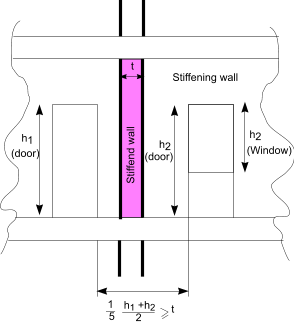
The minimum length of a stiffening wall with openings is shown in the sketch above.
The effective height of a wall including consideration of the above factors is
hef = ρn h ...n = 1.2. of 3 depending on the edge condition or stiffening.
For walls restrained and top and bottom by concrete floors spanning from both sides with bearing of at leas 2/3 t ..ρ2 =0,75
For walls restrained,as above but with timber flows or roofs ..ρ2 =1,00
For wall restrained at the top and bottom and stiffened by one vertical edge, with one free edge

For wall restrained at the top and bottom and stiffened by two vertical edges

Effective Thickness
The effective thickness tef of a single-leaf, double leaf , a shell bedded
wall and a grouted cavity wall should be taken as the actual thickness t.
The effective thickness of wall stiffened by piers is obtained from equation
tef = ρt.t
table showing values of ρt
Ratio of pier spacing Cen-Cen to pier width
Sp/Wp |
Ratio of pier depth to thickness of wall ( tp/t ) |
| 1 | 2 | 2 |
| 6 | 1,0 | 1,4 | 2,0 |
| 10 | 1,0 | 1,2 | 1,4 |
| 20 | 1,0 | 1,0 | 1,0 |

The effective thickness tef of a cavity wall with both leaves connected with wall ties is

kef is factor based on relative E values of leaves t1 and t2 (must be less than 2 )
The effective thickness tef of a cavity wall with only one leaf loaded can be based on the above equation provided
the wall ties are flexible
Resistance to lateral movement
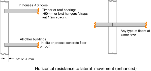
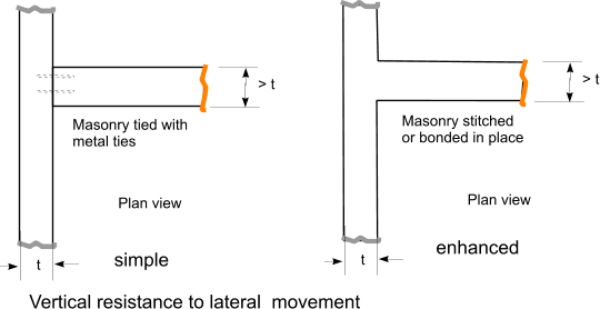
Slenderness ratio
The slenderness ratio ( He/te ) should not exceed 27. For walls less than 90mm thick in two story
building or more the slenderness ratio should not exceed 20
*************************************************************************
Masonry Walls subject to vertical loading
When analysing walls subject to vertical loading . The design should include for
Second order effects eg swaying
eccentricity of loading resulting from floors and stiffening walls
eccentricity resulting from construction deviations.
The bending moments should be considered and an initial eccentricity einit should
be allowed for the full height of the wall allowing for construction imperfections. einit may be assumed to be hef /450
Ultimate Limit State design
In calculating the vertical resistance of masonry walls it is assumed that
plane section remain plane and the tensile strength of the masonry perpendicular to the bed joints is zero.
At Ultimate limit design the vertical load NED shall be less , or equal to the design
value of the vertical resistance of the wall NRD i.r
NED ≤ NRD
The design value the vertical resistance of a single leaf wall per unit length =
NRD = φ.t.fd
Where φ is the capacity reduction factor at the top, bottom (φi) or
middle (φm) as appropriate.
t = wall thickness
fd is the design compressive strength of the masonry eg fk / γ m

Mid = design value of bending moment at the top or bottom of wall.
Nid = design value of vertical load at the top of bottom of wall
ehe = eccentricity at the top or bottom of wall ,if any, from horizontal load
einit = initial eccentricity
t = wall thickness
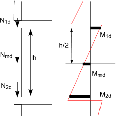
The reduction factor φm within the middle of the wall can be determined using the eccentricity
at the middle of the wall emk which is calculated using

values of φm are obtained by using the table below and interpolating as necessary.
Note: the table has been developed using the graph in the relevant standard. The values are based on E = 1000.fk.
table showing values of φm
| emk/t | hef/tef |
| 0 | 5 | 10 | 15 | 20 | 25 | 30 |
| 0,05 | 0,9 | 0,88 | 0,84 | 0,75 | 0,62 | 0,5 | 0,38 |
| 0,1 | 0,8 | 0,78 | 0,74 | 0,64 | 0,52 | 0,39 | 0,28 |
| 0,15 | 0,7 | 0,68 | 0,63 | 0,54 | 0,4 | 0,29 | 0,2 |
| 0,2 | 0,6 | 0,58 | 0,52 | 0,43 | 0,3 | 0,2 | 0,12 |
| 0,25 | 0,5 | 0,48 | 0,42 | 0,32 | 0,2 | 0,12 | 0,07 |
| 0,3 | 0,4 | 0,38 | 0,32 | 0,22 | 0,12 | 0,05 | 0,02 |
| 0,35 | 0,3 | 0,28 | 0,22 | 0,12 | 0,05 | 0,01 | 0,0 |
| 0,4 | 0,2 | 0,18 | 0,12 | 0,05 | 0,01 | 0,0 | 0,0 |
*************************************************************************
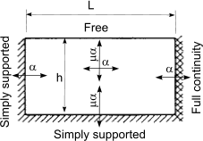
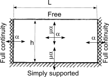
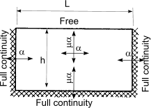
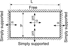
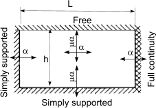
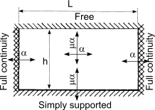
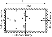
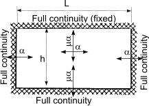
Calculation of design moments in laterly supported wall panels
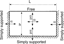
An approximate method of obtaining the design moments in a wall under lateral loading is to use
the following simple equations
When failure plane is perpendicular to bed joint
M = α.W k.γ f.L2 per unit height,
When failure plane is parallel to bed joint
M = μ.α.W k.γ f.L2 per unit height
| Wall arrangement | μ |
α |
| h/L |
| 0,3 |
0,5 |
0,75 |
1,00 |
1,25 |
1,5 |
1,75 |
 |
1,00 | 0,031 | 0,045 | 0,059 | 0,071 | 0,079 | 0,085 | 0,090 |
| 0,90 | 0,032 | 0,047 | 0,061 | 0,073 | 0,081 | 0,087 | 0,092 |
| 0,80 | 0,034 | 0,049 | 0,064 | 0,075 | 0,083 | 0,089 | 0,093 |
| 0,70 | 0,035 | 0,051 | 0,066 | 0,077 | 0,085 | 0,091 | 0,095 |
| 0,60 | 0,038 | 0,053 | 0,069 | 0,080 | 0,088 | 0,093 | 0,097 |
| 0,50 | 0,040 | 0,056 | 0,073 | 0,083 | 0,090 | 0,095 | 0,099 |
| 0,40 | 0,043 | 0,061 | 0,077 | 0,087 | 0,093 | 0,098 | 0,101 |
| 0,35 | 0,045 | 0,064 | 0,080 | 0,089 | 0,095 | 0,100 | 0,103 |
| 0,30 | 0,048 | 0,067 | 0,082 | 0,091 | 0,097 | 0,101 | 0,104 |
 |
1,00 | 0,024 | 0,035 | 0,046 | 0,053 | 0,059 | 0,062 | 0,065 |
| 0,90 | 0,025 | 0,036 | 0,047 | 0,055 | 0,060 | 0,063 | 0,066 |
| 0,80 | 0,027 | 0,037 | 0,049 | 0,056 | 0,061 | 0,065 | 0,067 |
| 0,70 | 0,028 | 0,039 | 0,051 | 0,058 | 0,062 | 0,066 | 0,068 |
| 0,60 | 0,030 | 0,042 | 0,053 | 0,059 | 0,064 | 0,067 | 0,069 |
| 0,50 | 0,031 | 0,044 | 0,055 | 0,061 | 0,066 | 0,069 | 0,071 |
| 0,40 | 0,034 | 0,047 | 0,057 | 0,063 | 0,067 | 0,070 | 0,072 |
| 0,35 | 0,035 | 0,049 | 0,059 | 0,065 | 0,068 | 0,071 | 0,073 |
| 0,30 | 0,037 | 0,051 | 0,061 | 0,066 | 0,070 | 0,072 | 0,074 |
 |
1,00 | 0,020 | 0,028 | 0,037 | 0,042 | 0,045 | 0,048 | 0,050 |
| 0,90 | 0,021 | 0,029 | 0,038 | 0,043 | 0,046 | 0,048 | 0,050 |
| 0,80 | 0,022 | 0,031 | 0,039 | 0,043 | 0,047 | 0,049 | 0,051 |
| 0,70 | 0,023 | 0,032 | 0,040 | 0,044 | 0,048 | 0,050 | 0,051 |
| 0,60 | 0,024 | 0,034 | 0,041 | 0,046 | 0,049 | 0,051 | 0,052 |
| 0,50 | 0,025 | 0,035 | 0,043 | 0,047 | 0,050 | 0,052 | 0,053 |
| 0,40 | 0,027 | 0,038 | 0,044 | 0,048 | 0,051 | 0,053 | 0,054 |
| 0,35 | 0,029 | 0,039 | 0,045 | 0,049 | 0,052 | 0,053 | 0,054 |
| 0,30 | 0,030 | 0,040 | 0,046 | 0,050 | 0,052 | 0,054 | 0,055 |
 |
1,00 | 0,013 | 0,021 | 0,029 | 0,035 | 0,040 | 0,043 | 0,045 |
| 0,90 | 0,014 | 0,022 | 0,031 | 0,036 | 0,040 | 0,043 | 0,046 |
| 0,80 | 0,015 | 0,023 | 0,032 | 0,038 | 0,041 | 0,044 | 0,047 |
| 0,70 | 0,016 | 0,025 | 0,033 | 0,039 | 0,043 | 0,045 | 0,047 |
| 0,60 | 0,017 | 0,026 | 0,035 | 0,040 | 0,044 | 0,046 | 0,048 |
| 0,50 | 0,018 | 0,028 | 0,037 | 0,042 | 0,045 | 0,048 | 0,050 |
| 0,40 | 0,020 | 0,031 | 0,039 | 0,043 | 0,047 | 0,049 | 0,051 |
| 0,35 | 0,022 | 0,032 | 0,040 | 0,044 | 0,048 | 0,050 | 0,051 |
| 0,30 | 0,023 | 0,034 | 0,041 | 0,046 | 0,049 | 0,051 | 0,052 |
| Wall arrangement | μ |
α |
| h/L |
| 0,3 |
0,5 |
0,75 |
1,00 |
1,25 |
1,5 |
1,75 |
 |
1.00 | 0.008 | 0.018 | 0.030 | 0.042 | 0.051 | 0.059 | 0.066 |
| 0.90 | 0.009 | 0.019 | 0.032 | 0.044 | 0.054 | 0.062 | 0.068 |
| 0.80 | 0.010 | 0.021 | 0.035 | 0.046 | 0.056 | 0.064 | 0.071 |
| 0.70 | 0.011 | 0.023 | 0.037 | 0.049 | 0.059 | 0.067 | 0.073 |
| 0.60 | 0.012 | 0.025 | 0.040 | 0.053 | 0.062 | 0.070 | 0.076 |
| 0.50 | 0.014 | 0.028 | 0.044 | 0.057 | 0.066 | 0.074 | 0.080 |
| 0.40 | 0.017 | 0.032 | 0.049 | 0.062 | 0.071 | 0.078 | 0.084 |
| 0.35 | 0.018 | 0.035 | 0.052 | 0.064 | 0.074 | 0.081 | 0.086 |
| 0.30 | 0.020 | 0.038 | 0.055 | 0.068 | 0.077 | 0.083 | 0.089 |
|
 |
1.00 | 0.008 | 0.016 | 0.026 | 0.034 | 0.041 | 0.046 | 0.051 |
| 0.90 | 0.008 | 0.017 | 0.027 | 0.036 | 0.042 | 0.048 | 0.052 |
| 0.80 | 0.009 | 0.018 | 0.029 | 0.037 | 0.044 | 0.049 | 0.054 |
| 0.70 | 0.010 | 0.020 | 0.031 | 0.039 | 0.046 | 0.051 | 0.055 |
| 0.60 | 0.011 | 0.022 | 0.033 | 0.042 | 0.048 | 0.053 | 0.057 |
| 0.50 | 0.013 | 0.024 | 0.036 | 0.044 | 0.051 | 0.056 | 0.059 |
| 0.40 | 0.015 | 0.027 | 0.039 | 0.048 | 0.054 | 0.058 | 0.062 |
| 0.35 | 0.016 | 0.029 | 0.041 | 0.050 | 0.055 | 0.060 | 0.063 |
| 0.30 | 0.018 | 0.031 | 0.044 | 0.052 | 0.057 | 0.062 | 0.065 |
 |
1.00 | 0.007 | 0.014 | 0.022 | 0.028 | 0.033 | 0.037 | 0.040 |
| 0.90 | 0.008 | 0.015 | 0.023 | 0.029 | 0.034 | 0.038 | 0.041 |
| 0.80 | 0.008 | 0.016 | 0.024 | 0.031 | 0.035 | 0.039 | 0.042 |
| 0.70 | 0.009 | 0.017 | 0.026 | 0.032 | 0.037 | 0.040 | 0.043 |
| 0.60 | 0.010 | 0.019 | 0.028 | 0.034 | 0.038 | 0.042 | 0.044 |
| 0.50 | 0.011 | 0.021 | 0.030 | 0.036 | 0.040 | 0.043 | 0.046 |
| 0.40 | 0.013 | 0.023 | 0.032 | 0.038 | 0.042 | 0.045 | 0.047 |
| 0.35 | 0.014 | 0.025 | 0.033 | 0.039 | 0.043 | 0.046 | 0.048 |
| 0.30 | 0.016 | 0.026 | 0.035 | 0.041 | 0.044 | 0.047 | 0.049 |
 |
1.00 | 0.005 | 0.011 | 0.018 | 0.024 | 0.029 | 0.033 | 0.036 |
| 0.90 | 0.006 | 0.012 | 0.019 | 0.025 | 0.030 | 0.034 | 0.037 |
| 0.80 | 0.006 | 0.013 | 0.020 | 0.027 | 0.032 | 0.035 | 0.038 |
| 0.70 | 0.007 | 0.014 | 0.022 | 0.028 | 0.033 | 0.037 | 0.040 |
| 0.60 | 0.008 | 0.015 | 0.024 | 0.030 | 0.035 | 0.038 | 0.041 |
| 0.50 | 0.009 | 0.017 | 0.025 | 0.032 | 0.036 | 0.040 | 0.043 |
| 0.40 | 0.010 | 0.019 | 0.028 | 0.034 | 0.039 | 0.042 | 0.045 |
| 0.35 | 0.011 | 0.021 | 0.029 | 0.036 | 0.040 | 0.043 | 0.046 |
| 0.30 | 0.013 | 0.022 | 0.031 | 0.037 | 0.041 | 0.044 | 0.047 |
 |
1.00 | 0.004 | 0.009 | 0.015 | 0.021 | 0.026 | 0.030 | 0.033 |
| 0.90 | 0.004 | 0.010 | 0.016 | 0.022 | 0.027 | 0.031 | 0.034 |
| 0.80 | 0.005 | 0.010 | 0.017 | 0.023 | 0.028 | 0.032 | 0.035 |
| 0.70 | 0.005 | 0.011 | 0.019 | 0.025 | 0.030 | 0.033 | 0.037 |
| 0.60 | 0.006 | 0.013 | 0.020 | 0.026 | 0.031 | 0.035 | 0.038 |
| 0.50 | 0.007 | 0.014 | 0.022 | 0.028 | 0.033 | 0.037 | 0.040 |
| 0.40 | 0.008 | 0.016 | 0.024 | 0.031 | 0.035 | 0.039 | 0.042 |
| 0.35 | 0.009 | 0.017 | 0.026 | 0.032 | 0.037 | 0.040 | 0.043 |
| 0.30 | 0.010 | 0.019 | 0.028 | 0.034 | 0.038 | 0.042 | 0.044 |
|


