| |
Fluids Index Drag on objects moving through fluids
Introduction..... Symbols..... Boundary layer..... Drag..... Drag 2D objects..... Drag - 3D objects .....
|
Introduction Fluid Flow Fluid flowing past an object tends to drag the object along in the direction
of fluid flow. If an object is moving through a stationary fluid the drag tends
to slow the object down. If the object is stationary in a flowing fluid the drag
tends to move the object in the direction of flow. The drag comprises two
components:
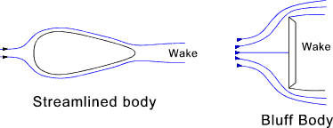
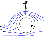
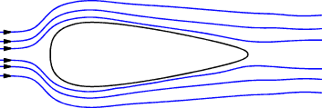
A perfect fluid flowing past an infinitely long cylinder is represented as streamlines which are arranged such that the flow through each streamline is fixed at Q . The streamlines flow over the cylinder and all forces are balanced front/back and top /bottom and there is therefore no form drag. A perfect fluid cannot transfer shear stress so there is no viscous drag. In real fluids there is a pressure build up on the front surface as the fluid is slowed and the streamlines are re directed round the cylinder. As the fluid flows over the cylinder the fluid separates into a wake which is a lower pressure region. There is therefore significant form drag. There is also skin-friction drag as the fluid passes over the surface. If the cylinder rotates, as shown below, the drag between the surface and the fluid results in the fluid flow as shown. The flow results in higher fluid velocities above the cylinder compared with the flow below the cylinder . Application of bernoulli's equation results a lower pressure above the cylinder and a consequent lift.
Symbols
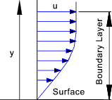
Boundary Layer and Wake Flow past a slender body or flat plate arranged parallel to the flow results in a
flow regime as shown below. The flows at the surface are brought to rest relative to the surface and
flows close to the surface are slowed. This effect reduces rapidly as the distance from the surface increases
until the flow is completely unaffected. The flow pattern may be split into two regions: A thin boundary layer
in which friction (viscous) drag forces are important and a region in which bernoulli's equation primarily
applies i.e. the total head is constant.
The boundary layer as formed by a fluid flowing along one side of the flat plate is initially laminar, as shown below. The velocity gradients are primarily due to the viscous drag near the surface of the plate. The velocity upstream of the plate and in the region outside the boundary layer is u n .
At the leading edge of the plate the fluid is retarded and the boundary layer is initiated. As more fluid
is slowed because of the viscous forces the boundary layer thickens. Initially the boundary layer includes
only laminar flow but as the boundary layer thickness increases the laminar layer loses stability and the flow
becomes less even. The point at which the laminar flow starts to deteriorate is called the transition point
and is at the start of a region called the transition region where the flow changes from laminar flow to turbulent flow.
At the plate surface a thin laminar sub-layer remains below the turbulent boundary layer. The sketch shows
the boundary layer thickness very much magnified relative to the length along the plate. The thickness of
the boundary layer on an aircraft wing may only be a few mm thick.
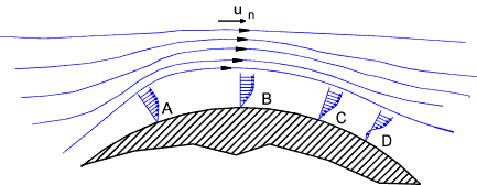
There is a point where the reverse pressure causes sufficient flow that the boundary layer velocity gradient
becomes zero and there is a tendency for the fluid to separate. In the figure above this is shown at point C and is
called the point of laminar separation. The result of this, so called,separation is to
impair the process of conversion between kinetic energy and pressure energy with internal fricitonal losses to heat.
A laminar boundary layer has less kinetic energy compared to a turbulent boundary layer and this effect is reduced if
a turbulent boundary layer flow can be encouraged. A golf ball is covered with dimples to encourage a turbulent boundary
layer and therefore delay the onset of separation
Drag notes. When calculating the total drag a very simple equation is used as shown below. This equation is not valid for relative fluid velocities approaching sonic velocity.
For bluff bodies A = The frontal area of the body facing the flow. For thin flat plates and similar shaped
items subject to primarily skin-friction A = the total surface area swept by the fluid flow (both sides) For wings
in aeronautical calculations A is the product of the wing span and the mean wing chord.
At low reynolds numbers (Re < 0,5)the inertial forces are negligible compared to the viscous forces
and the streamlines come together behind the cylinder. The drag is therefore
roughly proportional to u n. Drag is inversely
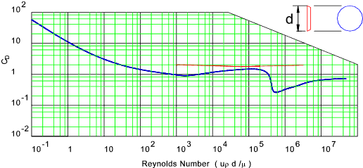
proportional to C D. Drag for Infinitely long PLATE and infinitely long CYLINDER Drag calculated is better calculated using the variation of the drag equation
The drag coefficient for a shape which is finitely long is affected by
fluid flow around the ends. This is illustrated by considering the plate
for reynolds number above 1000. The drag coefficient varies as follows for different
Length(L) to Breadth (d) ratios.
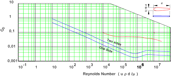
The drag coefficient is mainly friction drag (C f ).
The area is the length x width (l.d )
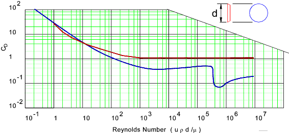
Drag for DISC and SPHERE<
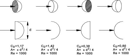
Drag factor for various objects
Drag for a human body = C D = 1 to 1,3 |
Useful Links
|
|
Fluids Index
