| |
Fluids Index Fluid Flow
Introduction.....
Symbols.....
Patterns of Flow.....
Types of Flow.....
Continuity Equation.....
Bernoulli's Equation.....
Stagnation Pressure.....
Real Fluids.....
Pressure in moving fluid.....
|
Introduction This webpage includes various notes relating to fluid flow and flowpaths and flow patterns at a very basic level. Symbols
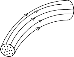
Patterns of Flow When considering the flow of a fluid it is often convenient to consider the flow as a number of imaginary curves along which individual particles of fluid flow. These lines are called streamlines or flowlines. fluid particles only flow along the streamlines and no particles cross the lines. A number of streamlines bundled together is termed a streamtube. he boundary of a streamtube is composed of streamlines and by definition of a streamline fluid can only enter and leave a streamtube at its ends.
The flow of fluid is always clearly three dimensional. However when
considering flow problems it is generally more convenient and practical to consider flow
as two dimensional or one dimensional. When considering flow along a pipe it
is convenient, and practical to consider the flow along the centreline of the pipe
run, that is
as one dimensional flow. The pressure loss, and variations of velocity etc are along
the pipe centre line. Macro pipe flow is more nearly two dimensional because the fluid
velocity varies across the diameter with zero velocity at the pipe wall and the maximum velocity
at the pipe centre. This problem is overcome in pipe flow calculations by
assuming the flow velocity as the mean velocity. Water flow over a long weir is
in reality three dimensional at the ends but can be considered as two dimensional
flow with corrections for the ends.
Types of Flow Internal flow is flow within the boundary walls.
Types of internal flow include pipe flow, channel flow, airflow in ducts.
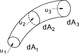
This type of flow is controlled using valves, fans , pumps. Continuity Equation The continuity equation is really a mathematical version of the principle of the conservation of mass as applied to fluid flow. If a region is defined in a fluid and steady flow conditions apply ..then. The rate at which mass enters the region = The rate at which mass leaves the region Considering a stream tube as shown below whose section is so small that the
velocity u and the density ρ do not vary across it. u 1ρdA 1 = u 2ρdA 2 = u 3ρdA 3 = Constant Considering a cross section of flow i.e. a pipe length with cross section A consisting entirely of stream tubes the equation above can be integrated as follows
The local velocity u is assumed to be normal to the local cross section and the density and velocity are constant over the entire local section then. uρA = Constant For fluids of constant density (incompressible fluids -liquids) with average flow u this reduces to uA = Constant = Q That is, under the conditions specified, when the area increases the velocity reduces and vice versa Bernoulli's Equation..Perfect Fluids The equation is an expression of the conservation of energy.
Initially the only forces considered are gravity, pressure and inertial forces. The viscosity
forces are assumed to be neglible. The fluid is assumed to be a perfect
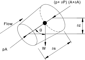
inviscid fluid under steady flow conditions. Newtons First law ...Every body continues in a state of rest or of uniform rectilinear motion unless acted upon by a force The relationships between the changes can be analysed using Newtons second law.. Newtons Second law ...The time rate of change of linear momentum of a body is proportional to the unbalanced force acting on the body and occurs in the direction in which the force acts. i.e Force = Mass.Acceleration. Applying Newtons first law to a small element of fluid within a single streamline of small cross section as shown below. The ends of the streamline are assumed normal to the centre line of the streamline . Considering the forces of pressure and gravity around the element and ignoring all other forces (viscosity , surface tension, magnetism, nuclear etc).
Upstream the pressure is p and downstream the pressure is (p + δp). δp may be negative. The forces at the side of the element vary but it will be assumed that the mean pressure is (p +kδp ) with k being some value less than one. Taking forces in the direction of flow and noting that the hydrostatic forces on the sides mean = (p +kδp ) are acting on the area δA - all other side forces are perpendicular to the axis and are ignored. The weight of the element = ρgAδs Resultant Force = pA - (p + δp)(A+ δA ) + (p + kδp)δA - ρgAδs cos θ ignoring second order of small quantities... Resultant Force = Aδp - ρgAδs cos θ The mass of the element is constant and therefore the resultant force must be equal to the mass times acceleration of the element in the direction of the force du/dt . ρAδs (du/dt) = Aδp - ρgAδs cos θ Now ( δs cos θ) = δz where z represents height above a horizonatal datum level.
Consider a particle moving along a steady flow streamline for which the velocity changes as the particle moves along the streamline e.g the velocity increases as the area of the streamline reduces. δu = [ du/ds ]δs. Therefore in the limit δt -> 0 the local acceleration with respect to time is
Therefore if (du/dt) is replaced by u(du/ds) the following equation results...
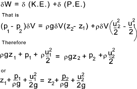
For fluids of constant density the equation can be integrated with respect to s as follows.
The resulting equation (in both forms) is known as Bernouli's equation and is probably the most widely used in fluids and hydraulics and explains many of the phenomena encountered in these areas of engineering. In the second form each term has the energy per unit weight ρg and has units [ML2 /T2] / [ML /T2] = [L]. The terms are identified as pressure head, velocity head, and gravity head.
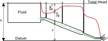
The figure below shows a hypothetical fluid system taking no account of friction losses in the pipe line. The gauge points show the pressure head at the connection point. The differences in level between the gauge level (red line) and the tank level represents the kinetic head.
The figure below illustrates the condition of a perfect fluid flowing out of reservoir through a sharp edged orifice. The fluid flows out as a free jet. The datum z is assumed to be at the centre line of the orifice.
At the inlet the total energy is equal to the hydrostatic head of the fluid h1 = p /( ρg ). At the exit from the orifice at the point of maximum velocity (vena contracta) the head is virtually = to the velocity head h2 = u2 /(2g). As h1 = h2 it is clear that the maximum velocity of the fluid flowing out of the tank is
Stagnation Point Considering bluff object located in a flowing fluid.
The off line flowstreams generally divert round the object as shown but the centre
flow stream is such that at the surface of the object the velocity in the direction of the flowsteam
= zero. This is called a stagnation point. Flow of real fluids..... reference First Law Of Thermodynamics Steady Flow Bernoulli's equation is fundamental to fluid flow analysis but it is subject to certain important simplifications. It assumes the fluid is inviscid and incompressible and that the flows are steady and relationships have been derived using newtons laws based on flows alone a single streamline. When considering the flow of real fluids it is necessary to include for energy losses and energy gains. The first law of thermodynamics is reviewed in outline on webpage Laws of Thermodynamics and basically identifies the transfer of energy over a complete cycle for a system as follows Δ Q = ΔE + ΔW Δ Q is the increase of energy supplied to a system, Δ E is the increase in the total energy of a system and Δ W is the mechanical work done by the system. In fluids the processes are flow processes and the first law is expressed in the form of the "steady flow energy equation as shown below..
q = net heat transferred to fluid per unit mass =
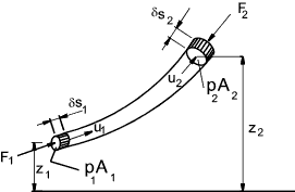
h f is the energy lost as a result of friction and is dissipated in increasing the internal energy of the fluid (e2 - e1 ) and as heat lost to the environment (q) Pressure in a moving fluid Bernoulli's theorem indicates that if the hydrostatic head (p/ρg +z) decreases then the fluid accelerates. Consider a streamtube (or pipe) as shown below.
Bernoulli's formula can be rewritten as
From the basic laws of motion ref. Dynamics
u1 is the initial velocity and u1 is the final velocity, s = distance , and a = acceleration. Therefore
The left hand side of this equation is the drop in the piezometric head - ( the head measured by a manometer type gauge). If the slope of this decrease in piezometric head is i then the head drop is iδs ..s being the distance along the streamtube or pipe.. Therefore....
According to Newtons second law acceleration = force/unit mass.
Form the intitial notes on bernoulli's principle above ref Bernoulli's Equation
This equation relates to forces in the direction of the axis of motion. For an incompressible fluid the piezometric head gradient ( i ) in any direction produces a corresponding force per unit mass in that direction equal to ( ig ). Assuming negligible viscous friction this is the only force acting on the fluid and can be equated to the corresponding fluid acceleration in that direction.
|
Useful Links
|
|
Fluids Index
