| |
Fluids Index Fluids -Curved Motion- Circulation & Vorticity
Introduction.....
Symbols.....
Curved streams.....
Fluid rotation.....
Free Vorticity.....
Forced Vorticity.....
Circulation.....
|
Introduction The notes on this page relate to fluid motion with curved streamlines and rotary fluid motion. The notes are of a very basic nature such that a mechanical engineer can obtain an understanding of the principles involved. The notes include sections on curved motion, fluid rotation, free vorticity, forced vorticity, and circulation. Symbols
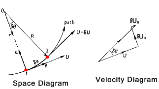
Motion in a curved path Consider the motion of a fluid element moving in a curved path moving from point 1 to point 2 see below.
Now if δs and δθ are small the following equations apply
The change in velocity normal to the path results from these expressions
The corresponding normal acceleration is therefore
The equation becomes exact at δs = 0
Ignoring the force due to gravity the force per unit mass in the n direction is ref Pressure in a moving fluid
The resulting equation of motion is therefore
As an example consider an incompressible fluid circulating steadily about a fixed axis. The value of i n at radius r is
The positive direction of the normal is opposite to that of the radius from the centre. Therefore the slope of the transverse Piezometric head is
Bernoulli's equation (H = z + (p /ρg ) +u 2/2g). The equivalent variations in total head (H) across curved stream-tubes may be evaluated . Its gradient in the radial direction from the centre of rotation is
Substituting u 2 /rg for the traverse piezometric head gradient d( p/ρg +z )/dr the following results
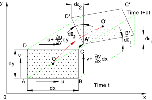
Fluid Rotation Consider a fluid element ABCD with sides dx and dy located at O which moves to location O' in time period dt and deforming in the process
AB in the x direction moves to A'B' in the process rotating dθ1 and AD in the y direction moves to A'D' in the process rotating dθ2
The angular velocities of AB and AD being ω1 and ω 2 respectively
The centre O has an angular velocity which is the average of (ω1 and ω 2 ) / 2
The fluid vorticity for the z axis is ζ is defined as
When the fluid vorticity ζ= 0 the fluid movement is called irrotational flow..
Free Vorticity
Circular fluid motions frequently occur in regions which are sensibly of constant energy
throughout. A typical example of this type of motion occurs when fluid in a vessel empties through
a small hole . In this case the liquid makes a rotary motion but its the water elements always face in the
same direction. The flow is irrotional
Integrating the the final expression between two radii results in the following :
That is
The corresponding pressure distribution across such a free vortex may be obtained from Bernoulli's equation since DH/dr = 9 for this motion, that is, H has the same value across each stream tube.
The constant c depends on the strength of the vortex... therefore
If the axis of rotation is vertical with z being constant at any radius then ρg (H-z) is simply the pressure at infinite radius say (pi )
That is
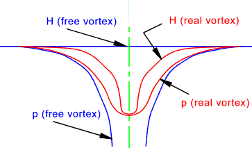
The figure below shows a section through a free vortex and a real vortex which includes real losses due to fluid friction. It is clear that at small radii for a ideal free vortex the velocity would approach infinity. In practice at small radii the fluid velocities are more proportional to the radius and not its reciprocal. At larger radii the agreement between the theory and practice is quite good
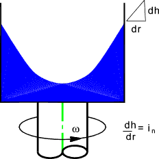
Forced Vorticity Fluid entrained in the rotating impeller of a centrifugal pump before the pump discharge valve is opened undergoes virtual forced vortex motion. A fluid contained in a rotating vessel, as shown below, also over time forms into a forced vortex. Such a vortex results whenever a fluid is whirled bodily about an axis with a constant angular speed.
In conditions of forced vorticity the linear velocity of the fluid is proportional to the radius of rotation, ... the fluid is being rotated as if it were a solid body i.e. u = r ω It has been shown that hydraulic gradient (piezometric head slope) in fluid i = a g ref Pressure in a moving fluid...A fluid in a circular motion has an accelaration of (u2 / r ) towards the centre of rotation. Therefore the piezometric slope towards the centre of rotation is in = an /g and an = u2 /r.. therefore
A forced vortex is such that the if the relevant liquid has a free surface (p/ρg = 0) then the radial slope of this surface (in) increases linearly with r..... the cross section is a parabola and the free surfaces forms a paraboloid..(see above figure).
The positive direction for the radius is outwards from the centre while that for the normal n is inwards towards the centre of rotation. Thus
Integration of this expression between two radii (r1 and r2 ) results in the following equations
Bernoulli's equation (H = z + p /ρg +u 2/2g). The equation below can thereofre be written in terms using bernoulli's equation as follow .
If H has a value H0 ar the rotation axis (when r = 0 and u = 0), then the value of H at any other radius is given by...
The surface profile results if (p/ρg)= 0. The equation corresponding to the surface profile is therefore ...
And z at any radius results from...
Now since the pressure variation across any horizontal plane is simply ρg time the head of liquid above it ...
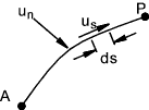
For a forced vortex both the pressure and total head increase parabolically with the radius. Circulation Consider a line AP of unit thickness in a flowing fluid.
The volume flow rate across the line = Qn and also the flow along the line can be expressed as Qs. These flows are obtained as follows
Now if the line is a fixed closed circuit the flow around the circuit is called the circulation ( Γ ) . . Convention is that positive circulations are ani-clockwise (ACW ) flows.
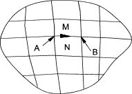
The circulation round a large circuit equals the sum of the circulations round components small circuits contained within the large circuit ( provided that the boundaries of all circuits are wholly in the fluid). This is illustrated by the figure below. The large circuit is subdivided into smaller ones. M and N are typical sub-circuits. The contribution of flow QsM along AB from circuit M along the common boundary is positive (ACW) while the contribution of flow from circuit N is QsN is negative and cancels out the contribution from M. Therefore all flows along common boundaries cancel each other and circulation then only consists of the flow round the periphery
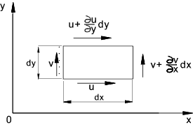
Now considering a small element in a flowing fluid as shown below..
The circulation is calculated as follows
Therefore
|
Useful Links
|
|
Fluids Index
