Hydraulics Index
Hydraulic Cylinder
|
Introduction Types of Cylinder Construction |
Cushioning Telescopic Mounting |
|
Introduction Hydraulic Cylinders are used to convert the pressure of hydraulic fluid to high force linear movement. At one end of the range of cylinder applications are small single acting cylinder of 10mm dia and 10 mm stroke, available for jig positoning and clamping. At the other end rams are available providing forces of many 1000 tonnes. The note sbelow are outline in nature to provide a basic understanding of the type and construction of hydraulic cylinders. Links are provided to hydraulic cylinder manufacturers with sites providing much more detailed information. Basic Calculations for obtaining the stroke force and speed of hydraulic cylinders are found on my webpage. Hydraulic Calcs
For many applications the hydraulic actuator which provides the linear movement is a cylinder. This provides motion
by extented or retracting the motion of a piston, or ram, within a cylinder. The movement of the piston /ram out
of the cylinder is usually the power stroke . For long stroke cylinders the limitation of the power stroke
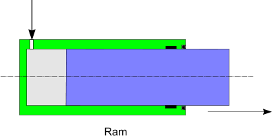
will be its strength of a member as a strut. Generally the retraction motion is not loaded. Types of Hydraulic Cylinders The simplest linear actuator is a Ram. Rams are generally used in applications for moving vertical heavy loads although horizontal Rams are used when suitable guides rods are provided to guide the motion. Ram-type cylinders are available for long strokes and are used on jacks, elevators and automobile hoists.
Hydraulic cylinders are further identified as
Single acting cylinders
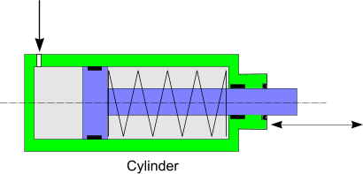
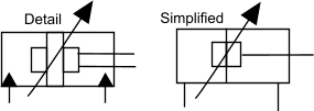
Single acting cylinders are pressurized at one end only while the opposite end is vented to the atmosphere or tank.
They are usually designed in such a way that a device such as an internal spring retracts them. Double acting cylinders.
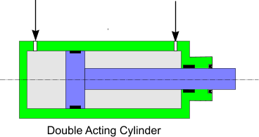
Double acting cylinders are the most commonly used hydraulic cylinders. The pressure can be applied to either port providing force
in extending and retracting. The force in extending the cylinder is generally greater than the retracton force. This
difference in effective area is in turn caused by the area of the rod that reduces the piston area during retraction.
Since more fluid is required to fill the piston side of the cylinder during extension, the operation is understandably slower.
During the retraction operation, the same amount of pump flow will retract the cylinder faster because of the reduced fluid volume
displaced by the rod. Construction The cylinder consists of five basic parts: two end caps (a base cap and a bearing cap) with port connections, a cylinder tube ( barrel ), a piston and the rod itself. This basic construction provides for simple manufacture as the end caps and pistons remain the same for different lengths of the same diameter cylinder. The end caps can be secured to the barrel by welding, through tie rods or by threaded connections. The end caps are generally made of cast iron or cast aluminum and incorporate threaded entries for ports.
The inner surface of the cylinder tube is very smooth to prevent wear and leakage. Generally, a seamless drawn steel
tube machined/honed to an accurate finish is used. In applications where the cylinder is used infrequently or involves
possible contact with corrosive materials, stainless steel, aluminum or brass may be used as the cylinder material.
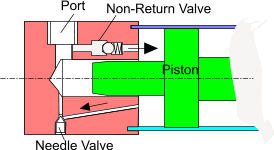
Cylinder cushioning End caps have to withstand shock loads at the extreme ends of piston travel. These loads arise not only from fluid pressure, but also from the kinetic energy of the moving parts of the cylinder and load. These shock loads can be reduced with cushioning systems built in the end caps. The principle of operation of the cushioning is shown in the sketch below. When the Piston aproaches the end of its stroke the flow to the output port is restricted by a projection on the piston entering the discharge route. The flow is then through small hole and via a needle valve which provides control of the cushioning effect. To allow smoothe full force movement of the piston away from the end cap a non-return valve is included.
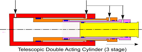
Telescopic cylinder The length of an hydraulic cylinder required to provide a sufficient stroke is sometimes too muuch for the space available. The installation length of a closed cylinder being is the total of the stroke plus the total length of the thickness of the piston, and ends For these cases telescopic cylinders are used . Telescopic cylinders are multi-stage units of two, three, four, five or more stages. In general telescopic cylinders are much more expensive than normal cylinders. Most telescopic cylinders are single acting (push). Double acting telescopic cylinders are specially designed and manufactured.
Mounting
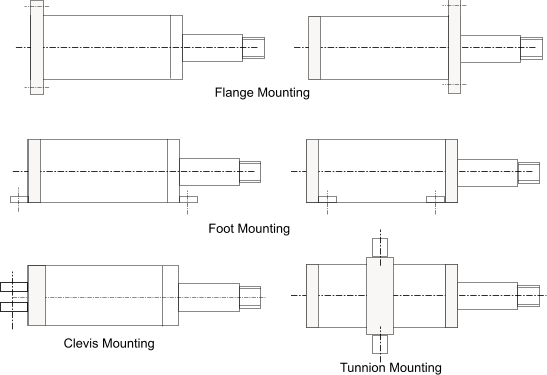
The mounting of the cylinder on the equipment is a very important factor. The mounting can arranged to support the cylinder
along the line of force e.g flange mounting - this providing a rigid mounting. The cylinder can also be mounted outside the line of force
e.g foot mounting . In this case the strength of the mounting should be sufficient to cater for the imposed moment.
The mounting may be along the line of force allowing angular movement e.g trunnion of clevis mounting. This type of mounting is best when the force moves in an
arc.
The Piston attachment also includes many variations allowing different degrees of rigidity.
|
Useful Links
|
|
Hydraulics Index
