Hydraulics Index
Hydraulic system calculations
|
Introduction This page includes a small number of basic notes and calculations to enable selection and sizing of various hydraulic components including .
The calculations are simplified and should only be used for initial design purposes.
Theoretical ideal values for the pumps and motors are calculated if 1(100%) is included for the efficiency . Actual efficiency values are obtained from suppliers
literature. Approximate efficiencies are provided in my notes of pumps and motors. I have created a excelcalcs spreadsheet for convenient access to all of the equations found on this page for members of Exelcalcs.com . This is located at ExcelCalcs.com calculation Simple Hydrostatic Transmission system calculations Units
Pipe sizing The recommended flow velocities
for hydraulic fluid are listed below.
The calculation of the fluid velocity is the flow ( q ) / pipe bore area ( Ai ) q = flow rate (litres/m ) Hydraulic Power due to pressure in flowing hydraulic oil The hydraulic power in the flowing fluid in a hydraulic piping is simply the flow rate (q) x the pressure of the fluid (p)
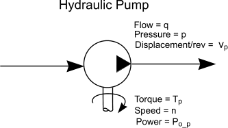
q = flow rate (litres/min ) Hydraulic Pump Calculations Notes on the various types of positive displacement hydraulic pumps are found on webpage Positive displacement pumps. The calculations below relate most specifically to Piston pumps, vane pumps and gear pumps operating a pressures in excess of 70 bar.
The pump fluid delivery is the pump displacement per revolution x the rotational speed
vp = displacement /rev (cc /rev )
The pump drive power required at the shaft =
vp = displacement /rev (cc /rev )
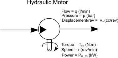
Hydraulic Motor Calculations
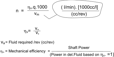
The speed is the fluid flow rate q divided the motor displacement/rev
vm = displacement /rev (cc /rev ) The motor drive power available at the shaft =
vm = displacement /rev (cc /rev ) The motor torque available at the shaft =
vm = displacement /rev (cc /rev ) Air Blast Cooler Calculation Three simple methods of specifying a cooler are provided.
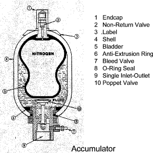
On arriving at a cooling requirement based at a circulating fluid flow rate, the air blast cooler is specified to remove the heat when the oil is at a desired maximum temperature and at the worst case ambient (air) temperature Heat developed based on motor efficiency pf = (1- ηm ) . pm / ηm pf = heat power to fluid Heat developed based on Input power This simply assumes that the overall efficiency of the system (pumps, motors, and valves result in losses of about 30%) pf = 0,3 . pe pf = heat power to fluid Heat developed based on temperature rise of reservoir pf = (ΔT. coil. ρoil.V )/ t pf = heat power to fluid Rating of Air Blast cooler p01 = m.pf /(T1 - T3) p01 = Thermal rating of cooler (kW /Degree (C)) Hydraulic Accumulator It may be necessary for an hydraulic system to work with a pump operating at constant speed while the motor or cylinder is not working at a steady speed. An accumulator acts as an hydraulic flywheel to even out the energy flow and enable a lower pump specification for a given duty. An accumulator is often placed close to the pump with a non-return valve preventing flow back to the pump, when the accumulator is used to smooth pulsations. It also helps protect the system from fluid hammer. An additional benefit is the surplus energy that can be stored while the pump is subject to low demand. The designer can often use a smaller-capacity pump relative to a short term high flow demand. The outflow of energy from a discharging accumulator can be greater, for a short time, than the pump could develop. The precharge is the pressure of the gas in the accumulator with minimum hydraulic fluid in the fluid side. A gas accumulator is precharged with nitrogen gas, to the desired pressure, when there is no hydraulic fluid in the accumulator. A rule of thumb for bladder accumulators is to set the precharge pressure to approximately 80% of the desired minimum hydraulic system pressure. A rule of thumb for gas piston accumulators is to set the precharge pressure to approximately of the of the desired minimum hydraulic pressure. hydraulic system pressure.
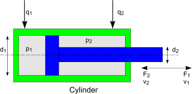
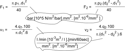
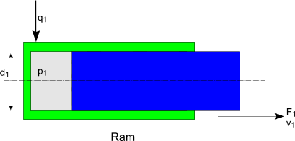
The useable volume Vu (litres) is the volume of fluid an accumulator will deliver as the system pressure falls from the maxiumum pressure pmax (bar) to the minimum presssure pmin (bar). Hydraulic cylinder The hydraulic force exerted by an extending Hydraulic Cylinder is calculated shown below. Please not the seal friction and fluid backpressure is not taken into account . The resulting forces will therefore be a little high The backpressure can easily be accounted for by calculating the resultant extending or retracting force as F1 - F2
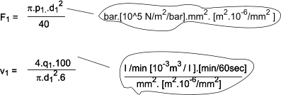
The hydraulic force produced by a ram or single acting cylinder is calculated using the same equations as shown below.
Heat Loss From Reservoir In operating a hydrostatic transmission system comprising pumps and motors and/or actuators there are significant mechanical losses. The result in the hydraulic fluid heating. If the losses are significant there may be a need to include a cooler in the system to remove the excess heat. This calculation provides a quick estimate of the natural losses to the environment. The simple calculation is based on the reservoir being located in an area such that the ambient air can freely circulate over all of its surfaces. I have obtained the value of C by considering a number of values found on the links below and on my webpage. Thermal design of Gearboxes Heat loss from reservoir Q = C.(Tf - Ta).A
Q = heat loss (kW) Approximate Power Loss due to head loss in piping It is possible to easily calculate the approximate head loss in the pressure piping of a hydrostatic system.
Using the methods identified webpage Pipe Flow
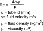
First it is necessary to calculate the Renold number for the flowing fluid
Mineral oil as used for hydraulics systems has a density of approx 850 kg/m3
It is normal to use a Moony chart to evaluate the friction factor f based on the tube roughness and
the Renold number.
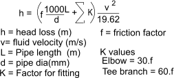
The head loss if fluid metres is simply calculated as follows
It will be necessary to detemine the flow path from the pump to the actuator estimate the pipe length and number of elbows and tees to complete the calculation for the pressure side. Then repeat the process for the return route which should have lower velocities and a larger diameter The pressure loss and the power loss is calculated from the total pipe head loss as follows
Example : Viscosity = 57cP, Density = 850 kg/m3. The return leg from the motor to the reservoir is 25 mm i.dia, 20m long, and includes 3 elbows and 2 tees . The flow rate is 50 litres/min and the oil is grade ISO 68 at 40 deg.C Viscosity = 57cP, Density = 850 kg/m3. Total power loss as pipe resistance = 0,24 + 0,10 = 0.34 kW. | ||||||||||||||||||||||||||||||||||||
Useful Links
|
|


 >
>

