Hydraulics Index


Positive Displacement Pumps

Introduction

This page is a subset of the page with the same title in the pumps section of this website. Rotary Positive Displacement Pumps The pumps described, in short notes , on this page are pumps used for power transfer duties as used for high pressure hydrostatic systems for hydraulic lifting 
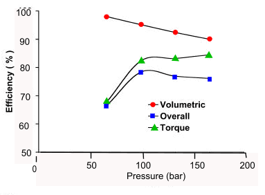
equipment, vehicles, elevators, machine tools , aeroplane controls and other systems requiring servo systems .

The notes are outline in nature and it is recommended that for production of detail designs and specifications suppliers literature is referenced. I have provided some links at the foot of this page to relevant pumps suppliers.

Basic Calculations relating pump fluid flow, power and, shaft torque are found on my webpage. Hydraulic Calcs


Positive Displacement Pump Descriptions

These notes include descriptions of the following pump types

  1. External Gear Pump
  2. Internal Gear Pump
  3. Lobe Pump
  4. Sliding Vane Pump
  5. Piston Pump

Below are identified various types of positive displacement pumps which are used in hydtrostatic drive systems with basic notes identifying operating information.


External Gear Pump

The gear pump is used for fluid transfer and power transfer and process duties.  The gear pump is widely used in the agricultural and mobile vehicle industry for hydraulic transmission systems.

The pump can be used for transferring a wide variety of fluids depending on the materials of construction.

The pump includes two gears one gear is driven by the prime mover.   The pump bearings are generally provided with internal bearings and packed glands or mechanical seals.   The most popular gear types are straight spur.  These can be noisy and subject to vibration if they are not manufactured to high standards.   Helical gears can be used to minimise vibration but high side loads result.   The used of double helical gears to eliminate side loads results in expensive costly units.

These pumps are reliable low cost units which can be run for long periods if operated correctly.  They have good high pressure operating characteristics.  Close tolerances are required between the internal components for the pump to operate effectively

The gear pump has moderate efficiency..

These pumps can transfer fluids at reasonable flow rates at developed heads of up to 200 bar.  For pressures above 50 bar the pumps have to be specially designed with hydraulic balancing.  These pumps have moderate self priming capabilities

External Gear Pump


Approx Efficiencies of a typical gear pump /motor


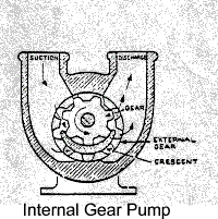
Internal Gear Pump

The internal gear pump has similar characteristics to the external gear pump.   The pump has improved suction and delivery characteristics and is smoother in operation.    The pump is based on an external gear located within, and meshing with, a larger internal gear.    A crescent vane is included to seperate the inlet volume from the discharge volume between the two gears.

The internal gear pump is however more complicated and expensive to manufacture and maintain than the external gear pump.

The internal gear pump can develop liquid pressures of 200 barg.

Note: Gerotor pumps very similar to internal gear pumps without the vane .    The operation of tyhe gerotor pump is similar to that of an internal gear pump. The inner gear rotor (gerotor element) is power driven and draws the outer gear rotor around as they mesh together. This forms the inlet and outlet discharge pumping chambers between the rotor lobes. The tips of the inner and the outer lobes make contact to seal the pumping chambers from each other. The inner gear has one tooth less than the outer gear, and the volumetric displacement is determined by the space formed by the extra tooth in the outer gear.

Internal Gear Pump


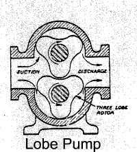
Lobe Pump

This pump is based on two parallel rotors located within a shaped case.   The rotors include a number of lobes these are arranged such that as the rotors are rotated they contain spaces which increase and reduce in volume.   Fluid enters these spaces through the inlet connection and is trapped as the rotors rotate.   The fluid is compressed and forced out of the discharge connection as the rotor continues to rotate.   This pump is effectively a development of the external gear pump.

The rotors are synchronised by external timing gears and therefore the internal contact between the lobes is a sealing contact and not a driving contact.   The rotors need not actually contact.

Various shapes of rotor are used, the tri-lobe rotor is probable the most popular.  The lower the number of lobes the better the pump is for handling viscous and solids laden fluids.  The rotor can be made from a wide selection of materials from exotic steel to synthetic rubber-with steel internal support.  When soft rotors are used this type of pump can achieve high levels of volumetic efficiency.

This type of pump includes for relatively low internal fluid velocities with low level of shear.   The resulting flow includes some level of pulsation.   The pump can run dry, subject to the design of the bearings and the pump is self priming especially if the rotors are wetted.   As the pump has clean internal surface with few crevices the pump can be used for hygiene related applications.

The pump can transfer fluid at flowrates up to 500 m3/hr (200 dia pump) and can deliver total heads of 20 bar.

Lobe Pump


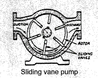
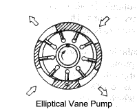
Sliding Vane Pump

The vane pump includes a ring mounted inside a cylindrical case   The ring includes a number of radial slots in which are located sliding vanes.  The ring is mounted eccentric to the case and the vanes are designed to press against the inside wall of the case.  The vanes are forced against the wall by hydraulic pressure or spring force or due the the centrifugal force resulting as the ring is rotated.

The prime mover is use to rotate the ring and liquid flow into compartments between the vanes and the case inner circumference.  As the ring rotates the liquid is trapped in the compartment and is then compressed and forced out through the discharge connection.

The older designs of vane pump are based on an eccentric ring as described above .  These are not hydraulically balanced and are thus limited in the hydraulic presssure which can be developed.  More modern designs include for an elliptical inner ring which results in two pressure cycle per revolution.  These pumps can develop much higher pressures at high rotational speeds.

The vanes outer edges are subject to continuous wear and the vanes need to be replaced after periods of continuous use.   Modern pumps are design for convenient maintenance by having the internal components design as cartidges.   The hydraulic circuit based on these pumps should include a relief valve.    This design of pump include a large number of mechanical parts related to its duty.

In transfer duties these pumps can develop high suction heads.  They are smooth operating and have higher efficiency compared to gear pumps.   They can handle suspended non-abrasive solids.  Certain designs can tolerate significant vane wear. (carbon vanes)

This type of pump when pumping hydraulic oil can develop head of 200 barg.

Sliding Vane Pump

Elliptical Vane Pump


Approx Efficiencies of a typical vane pump /motor


Rotary Piston Pumps

This general type of pump includes a number of variations some of which are described below.

  1. Radial Piston Pump
  2. Swashplate Piston Pump
  3. Wobble Plate Pump
  4. Bent Axis Piston Pump
General

The pumps are extensively used for power transfer applications in the off shore , machine tool industry, power transmission , agricultural, aerospace and construction industries,...etc.etc. 
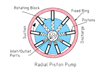
All of these pumps work on a similar principle.

The pump includes a block with a number of symmetrically arranged cylindrical pistons around a common centre line.   The pistons are caused reciprocate in and out under the action of a separate fixed or rotating plate (axial piston pump) or an eccentric bearing ring (radial piston pump) or some other mechanical feature.   Each piston is interfaced with the inlet and outlet port via a special valve arrangement such that as it moves out of its cyclinder it draws fluid in and as it moves back it pushes the fluid out.   The pumps are engineered to allow rotational speeds from less the 1 RPM to over 25,000RPM.


Radial Piston Pumps.

Radial Piston pumps include a rotating cylinder containing equally spaced radial pistons arranged radial around the cylinder centre line.  A springs pushes the pistons against the inner surface of an encircling stationay ring mounted eccentric to the cylinder.      The pistons draw in fluid during half a revolution and drive fluid out during the other half. The greater the ring eccentricity the longer the pistons stroke and the more fluid they transfer.

Radial Piston Pump


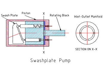
Swashplate Pumps.

Swashplate pumps have a rotating cylinder containing parallel pistons arranged radially around the cylinder centre line.   A spring pushes the pistons against a stationary swash plate located at one end of the cylinder , which sits at an angle to the cylinder.   The pistons draw in fluid during half a revolution and drive fluid out during the other half. The greater the swashplate angle relative to the cylinder centre line the further the longer the pistons stroke and the more fluid they transfer.

Swashplate Pumps


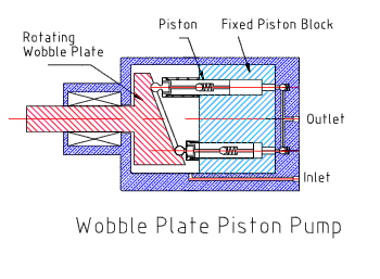
Wobble Plate Pumps.

This pump includes a stationary piston block containing a number parallel pistons arranged radially around the block centre(at least five). The end of each piston is forced against a rotating wobble plate by springs. The wobble plate is shaped with varying thickness around its centre line and thus as it rotates it causes the pistons to reciprocate at a fixed stroke.   The pistons draw in fluid from the cavity during half a revolution and drive fluid out at the rear of the pump during the other half.    The fluid flow is controlled using non-return valves for each piston.

These pumps can generate pressures of up to 700 bar.

Wobble Piston Pump


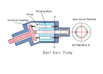
Bent Axis Pump.

Bent axis piston pumps have a rotating cylinder containing parallel pistons arranged radially around the cylinder centre line.   The cylinder is driven by an shaft which is arranged at an angle to the cylinder axis.    the shaft includes a flange with a mechanical connection to each piston.    As the shaft rotates the pistons are made to reciprocate over a stroke based on the relative angle of the shaft and cylinder.

Bent Axis Pump


Approx Efficiencies of a typical piston pump /motor

Useful Links

  1. Glossary of Pumps.. Animated pictures and detailed sections for most types of pumps
  2. Wikipedia Hydraulic Pumps.. Detailed notes


Hydraulics Index