Basic Notes on Risk Assessments
The risk is the probability or chance that the hazard will lead to injury.
A hazard is sometimes unavoidable i.e. a vee belt drive, a chain drive, a furnace.... all present
hazards. The risk of harm from these hazards is however controllable.
It is a HSE requirement and a requirement of all European directives that workers in industry
and the public are protected from harm and it is a designers responsibility to ensure that
machines are designed to be safe. An important part of the design process is to complete
a risk assessment. The Machinery Directive "98/37/EC" (ref link below)
identifies requirements in this direction.
The hazard analysis / risk assessment is outlined in the standard BS EN 1050:1997
"Safety of machinery. Principles for risk assessment" . The purpose of
this standard is to provide guidance for the safety of machinery and the type of documentation required in verifying a risk
assessment. This standard also describes procedures for identifying
hazards, estimating and evaluating risk.
The following methods of completing risk assessments are defined..
- What-If method
- Failure Mode and Effect Analysis (FMEA)
- Hazard and Operability Study (HAZOPS)
- Fault Tree Analysis (FTA)
- Delphi technique
- Defi method
- Preliminary Hazard Analysis (PHA)
- Method Organised for a Systematic Analysis of Risks
(MOSAR)
|
Three standards providing guidance on machine safety provisions including guards and controls are
listed below
- BS EN ISO 12100:2010 Safety of machinery. General principles for design. Risk assessment and risk reduction
- BS EN 953:1998 Safety of machinery. Guards. General requirements for the design and construction of fixed and movable guards
- BS EN 954-1:1997 Safety of machinery. Safety related parts of control systems.
General principles for design.
|
Risk assessment is a series of logical steps in conducting
the examination of the hazards associated with machinery.
Risk assessment is followed, whenever necessary, by risk reduction.
Risk analysis provides information required for the risk evaluation,
which allows an evaluation to be made on the safety of machinery.
Fault Tree Analysis
The notes below are outline only ..More detailed information is provided in the links below..
A fault trees is a graphic model of the pathways within a system that can lead to a foreseeable,
undesirable fault event. The pathways interconnect contributory events
and conditions, using standard logic symbols. Numerical probabilities of occurrence can be
entered in the model to evaluate probability of the foreseeable,undesirable event.
Symbols..
Symbols are used in fault tree analysis to represent events and the logical interface
between the events. Most fault tree analyses can be carried out with
just four symbols..

- Top Event...This is the undesirable event towards which the fault tree logic paths flow
- Intermediate Event...System state following previous logic events
- Or Gate...Logic gate producing an output if there are any inputs
- And Gate...Logic gate producing an output only if all inputs co-exist
- Basic Event...Basic fault identifying limit of analysis. Lower level generating faults are not included
|
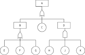
Typical Diagram

In the above fta logic diagram the intermediate event "B" results if basic events E or F or G
occur. The intermediate event D results if basic events H and J and K occur simultaneously.
The top fault event results if events B or C or D occur.
- At each logic gate input the identified faults should be independent.
- The identified basic /intermdeiate must be sufficient to immediately cause the resulting higher level event.
|
Quantifying Failure probabilities
For system based on an "OR" gate with two initiating fault events
A & B the probability of a system failure Pf = PA +P B - P A . P B
For system based on an "AND" gate with two initiating fault events
A & B the probability of a system failure Pf = P A.PB
Example;
An "OR" gate with two initiating events A with a probability of failure of 10-3 per year
and B with a probability of failure o 10-2 per year will result in a system failure probability of 11 * 10-3 per year
An "AND" gate with similar events will result in a system failure probability of 10-5 per year
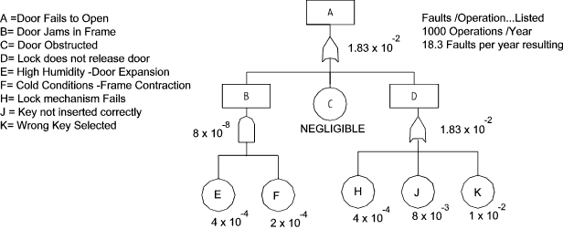
Example fault tree with failure data included...

Additional Symbols

- The exclusive "OR" produces an output occurs when only one input occurs
- The ordered "AND" produces an output occurs all inputs occur in an ordered sequence
- The undeveloped event is simply an failure event at a very simple level which could be developed in a separate fta tree
- The external event is normal event which could cause a fault
|
| 


