Machine_Parts_Index
Flywheel Basics
More details on Flywheel design are to be found in the links below the table
|
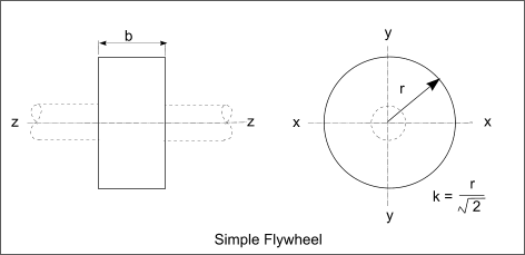
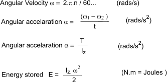
Introduction When a mass at rest is rotated it acquires kinetic energy. Slowing the mass down or bringing it to rest is achieved by removing kinetic energy. An engineered rotating mass designed specifically to store energy as a result of it motion is called a flywheel. The energy storage system involving a flywheel as its primary unit is called a Flywheel Energy Storage system (FES). Flywheels are used to balance up the energy flow from a smooth running machine delivering energy at a relatively constant level to a load which is varying. Flywheels are also used to produce continuous smooth outputs from engines which are inherently cyclic in nature. Flywheels are generally heavy discs rotating at speed. A flywheel is basically a mechanical version of an electric capacitor when used for short term load balancing. When used for storing energy it is equivalent to a battery. The energy stored in a rotating flywheel is simply found by use of the equation E = Iz.ω 2 / 2 ........ Iz = M.k2 /2
Typical FES applications include - As punch and shear presses when short bursts of energy are required on the punch strokes. For typical present day applications when the flywheel is used for short term energy balancing and smoothing the design process is generally relatively basic. However for modern FES applications involving replacement of other forms of energy storage e.g batteries, the designs become relatively high tech and the following factors need to be considered. - Bearing friction- Magnetic levitition bearings / Air bearing etc
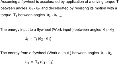
Below are provided some basic equations with metric units.
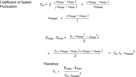
It is often necessary to determine the size of Flywheel (Iz ) necessary to ensure the speed is maintained within a certain range i.e angular velocity limited to a range ω min to ω max When the kinetic energy level varies between values of Emin and Emax
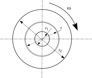
A flywheel can often be simplified to a rotating ring to enable the determination of the stresses resulting from the rotation. The theory involved in determining the stressses in a thick walled cylinders can be used, the primary difference being that they are caused by inertial forces acting on the ring . The following conditions apply in these assumptions.
The theory supporting these notes in provided, in basic form, on webpage. Rotating disks and Cylinders... Members of excelcalcs.com can upload a spreadsheet including all of the equations below at ExcelCalcs.com calculation Stresses in Rotating Disks & Rings ...
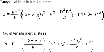
The tangential and radial stresses at radius r resulting from rotation of a ring with and outside radius = r2 and and inside radius = r1 rotating at an angular velocity ω are found using the following equations
The maximum tangential stress occurs at inside of the hole and equals
The maximum radial stress occurs at radius r = √(riro ) and equals
|
Links to Cam Design
|
|
Machine_Parts_Index
