| |
Shock Absorbers
These notes are very basic ..More detailed notes on shock absorber /isolation systems will be provided at a future date.
More details on Shock Absorber design are to be found in the links below the table
Introduction..... Shock absorber types..... Comparing Spring and Compensating Type..... Determining Energy to be absorbed .....
|
Introduction Reference Impact loads/stresses Impact Loading Shock Absorber types There are a number of different methods of converting an impact /collision into relatively smooth cushioned contact..
Simply locating metal springs to absorb the impact loads are a low cost method of reducing the collision
speed and reducing the shock loading. They are able to operate in very arduous
conditions under a wide range of temperatures. These devices have high
stopping forces at end of stroke. Metal springs store energy rather than dissipating it
. If metal sprint type shock absorbers are used then
measures should be provided to limit oscillations ---Metal spring are often used with viscous dampers .
These are a low cost options for reducing the collision speed and reducing the shock
loading and providing system damping. They are conveniently moulded to suitable shapes.
These devices have high stopping forces at end of stroke with significant internal damping.
Elastomeric dampers are very widely used because of the associated advantages of low cost and mouldability
together with performance benefits. The inherent damping of elastomers is useful in preventing
excessive vibration amplitude at resonance - much reduced compared to metal springs. This type of shock absorber is based on a simple hydraulic cylinder. As the
piston rod is moved hydraulic fluid is forced through an orifice which restricts flow
and consequently provides a controlled resistance to movement of the piston rod. Collapsing Safety Shock Absorbers These are single use units which are generally specially designed for specific duties. They are designed such that at impact they collapse and the impact energy is absorbed as the materials distort in their inelastic/yield range. They therefore are more compact compared to devices based on deflections within their elastic range. Air ( Pneumatic) Springs These devices use air as the resilient medium . Air has a high energy storage capacity
compared to metal or elastomer materials. For duties with high loads and
deflections the air spring is generally far more compact that the equivalent metal or
elastomer device. Self compensating Hydraulic These devices are similar to the hydraulic dashpot type except that a number
of orifices are provided allowing different degrees of restriction throughout
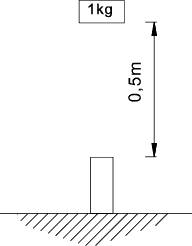
the stroke. Shock Absorber Comparison These notes identify the high force that can result from and impact and the show the reduction in force by use of a spring and a compensating hydraulic shock absorber. The example is provides as a general illustration and is very much simplified. Force resulting from impact with No shock absorber included Considering a very simple duty of dropping a 1 kg load through 0,5 m onto a machine
element represented by a short steel column 0,1m dia by 0,2m long made form steel.
The stiffness of the column k = AE / l. A = 0,00785m2 The stiffness of the column k is the Load /unit deflection is calculated as.. k = 0,00785 . 21 . 1010 / 0,2 = 0,825 . 1010 N/m
To calculate the maximum force resulting from the dropped load assuming conservation of energy. E 1 = M.g.h = 1 . 9,81 . 0,5 = 4.905 Nm. This equals the strain energy absorbed by the load at impact The strain energy absorbed = Pmaxδmax /2
= Pmax2 / 2 k Note: This is a transient (shock load) with an associated transient deflection of the impact surface. Therefore to calculate the maximum force developed Pmax Pmax = Sqrt (2.E1.k) = Sqrt (2 . 4,905 . 0,825 . 1010 ) = 284 kN
This value can also be determined in a similar manner using the principles established on page Impact Loading
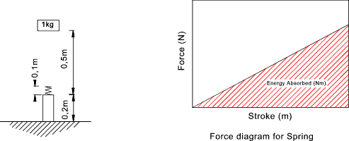
Maximum force Resulting From Use of Spring If a spring with a stroke of 0,1m is located on the top surface as shown below. The spring is rated to absorb all of the energy resulting
from the dropped load.
The resulting maximum force is determined as follows. Energy to be absorbed = E1 = M.g.h. = 4.905 Nm Use of the spring has reduced the maximum force by a factor of 3000.
However the spring is now exerting an upward force
which will cause the load to rebound upwards. Detailed analysis of the system
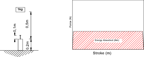
response is required to arrive at the total motion history of this event Maximum force Resulting From Use A compensating Hydraulic Shock absorber If a Shock absorber with a stroke of 0,1m is located on the top surface as shown below
The resulting maximum force is determined as follows. Energy to be absorbed = E1 = Mgh. = 4.905 Nm
The energy has been dissipated in heating up the hydraulic fluid in the shock absorber. When the load
has come to rest the system is in a stable state. The maximum force transmitted
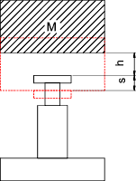
to the column during impact is significantly less than that experienced by without the shock absorber. Shock absorber duty requirement The capacity of a shock absorber is determined by calculating the energy to be absorbed. The calculation of the energy absorbed is shown in the notes below which illustrate some of the different applications. Free falling mass;
Assessing the shock absorber requirements. E 1= Mgh. The additional energy to be absorbed in the shock absorber stroke E 2= Mgs. The total energy to be absorbed by the shock absorber . E t= E 1+ E 2 The total energy to be absorbed/hour by the shock absorber. (n = number of operations per hour). E th= E tn The velocity at impact on the shock absorber. v d = Sqrt(2gh) The equivalent weight to be supported by the shock absorber Me= 2M / v d2 Horizontal moving mass;
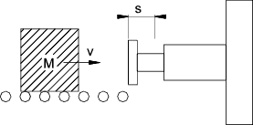
Assessing the shock absorber requirements. E 1= Mv2/ 2 The additional energy to be absorbed in the shock absorber stroke . E 2= 0 The total energy to be absorbed by the shock absorber E t= E 1+ E 2 The total energy to be absorbed/hour by the shock absorber. (n = number of operations per hour) E th= E tn The velocity at impact on the shock absorber v d = v The equivalent weight to be supported by the shock absorber Me= M Horizontal moving mass with constant propelling force; Assuming moving friction = 0
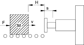
The energy to be absorbed at first contact with the shock absorber E 1. E 1= Mvd2 /2 The additional energy to be absorbed in the shock absorber stroke . E 2= Fs The total energy to be absorbed by the shock absorber. E t= E 1+ E 2 The total energy to be absorbed/hour by the shock absorber. (n = number of operations per hour). E th= E tn The velocity at impact on the shock absorber.
The equivalent weight to be supported by the shock absorber. Me= 2.Et / v d2 Mass Moving down incline Assuming moving friction = 0
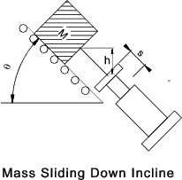
The energy to be absorbed at first contact with the shock absorber E 1 E 1= Mgh = Mvd2 / 2. The additional energy to be absorbed in the shock absorber stroke. E 2=M g s sin θ The total energy to be absorbed by the shock absorber. E t= E 1+ E 2 The total energy to be absorbed/hour by the shock absorber. (n = number of operations per hour). E th= E tn The velocity at impact on the shock absorber. vd = Sqrt (2 g h) The equivalent weight to be supported by the shock absorber . Me= 2.Et / v d2 Mass Moving down incline with downward force Assuming moving friction = 0
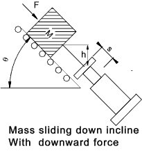
The energy to be absorbed at first contact with the shock absorber E 1. E 1= (F sin θ + Mg)h = Mvd2 / 2. The additional energy to be absorbed in the shock absorber stroke E2 = (F + Mg sinθ) � s The total energy to be absorbed by the shock absorber. E t= E 1+ E 2 The total energy to be absorbed/hour by the shock absorber. (n = number of operations per hour). E th= E tn The velocity at impact on the shock absorber.
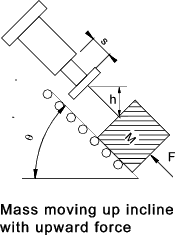
The equivalent weight to be supported by the shock absorber . Me= 2.Et / v d2 Mass Moving up incline due to upward force Assuming moving friction = 0
The energy to be absorbed at first contact with the shock absorber E 1. E 1= (F sin θ - Mg)h =Mvd2 /2 The additional energy to be absorbed in the shock absorber stroke. E2 = (F - M g sinθ) � s The total energy to be absorbed by the shock absorber . E t= E 1+ E 2 The total energy to be absorbed/hour by the shock absorber. (n = number of operations per hour). E th= E tn The velocity at impact on the shock absorber.
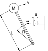
The equivalent weight to be supported by the shock absorber . Me= 2.Et / v d2 Swinging Mass Without Propelling Torque The swinging mass is assumed to be swinging on a horizontal plane..
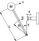
The energy to be absorbed at first contact with the shock absorber E 1 E 1= Mv2/2 = Iω2 /2 The additional energy to be absorbed in the shock absorber stroke . E2 = 0 The total energy to be absorbed by the shock absorber . E t= E 1+ E 2 The total energy to be absorbed/hour by the shock absorber. (n = number of operations per hour). E th= E tn The velocity at impact on the shock absorber vd = vR/L = ωR The equivalent weight to be supported by the shock absorber . Me= 2.Et / v d2 Swinging Mass With constant Propelling Torque T The swinging mass is assumed to be swinging on a horizontal plane.
The energy to be absorbed at first contact with the shock absorber E 1. E 1= Mv2/2 = Iω2 /2 The additional energy to be absorbed in the shock absorber stroke. E2 = Ts /R The total energy to be absorbed by the shock absorber . E t= E 1+ E 2 The total energy to be absorbed/hour by the shock absorber. (n = number of operations per hour). E th= E tn The velocity at impact on the shock absorber. vd = vR/L = ωR The equivalent weight to be supported by the shock absorber. Me= 2.Et / v d2 |
Links to Spring Design
|
|
Machine_Parts_Index
