| |
| These Pages include various standards. To confirm the status of any standard, identify the replacement standard if it is obsolete and/or purchase the standard please use. It is also possible to become a BSI member and obtain copies of the Standards at much reduced prices. |
Symbols used in Pneumatic / Hydraulic Circuit diagrams
|
Introduction
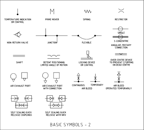
The symbols shown below are generally based on Basic Symbols
Following are examples of the basic symbols 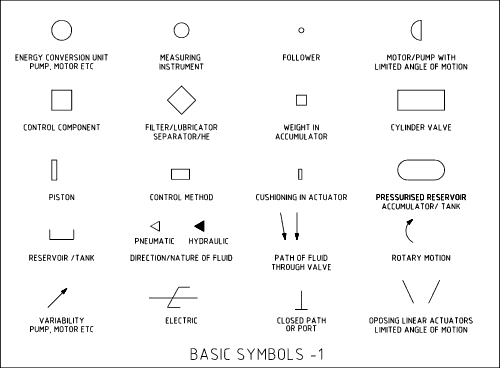
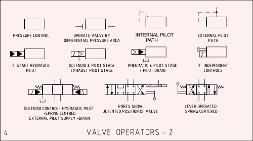
Valve Operators
Following are typical symbols associated with Valve
Operators 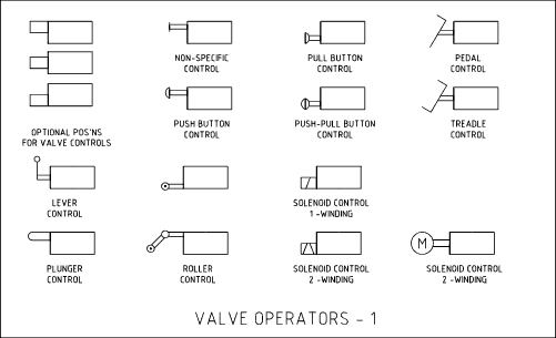
Energy Conversion Devices
Following are typical symbols associated with Pumps
and Motors 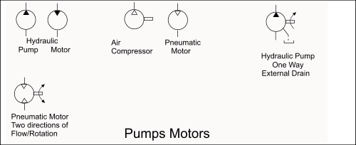
Instruments
Following are typical symbols associated with
Instruments 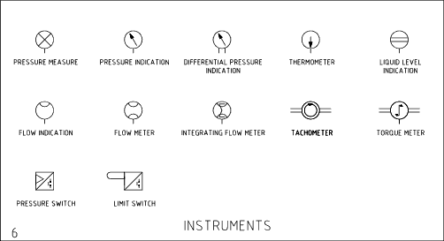
Fluid Conditioning
Following are typical symbols associated with Air
Conditioning Units 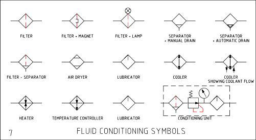
Fluid Cylinders
Following are typical symbols associated with Fluid
Cylinders 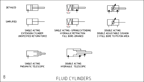
System Pressurisation
Following are typical symbols associated with Fluid
System Pressurisation 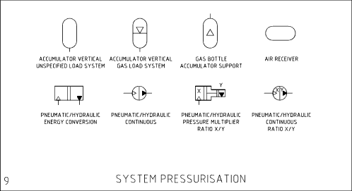
|
Links Providing information on Drawing Diagrams and
Symbols
|
|
This Page is being developed
Send Comments to Roy Beardmore