| |
Drawing Page
|
Reference Standards BS ISO 1101:1983 Technical Drawings - Geometrical tolerancing - Tolerancing of form, orientation,
location and run-out - Generalities, definitions, symbols, indications on drawings The notes below relate to use of geometric tolerances on drawing. The notes are
outline in nature to provide general guidance. This subject is complex
and it is wise to consult the standards and have a clear understanding of what is required
when including geometric tolerances on technical drawings. There are clear differences
between ANSI Y14.5 and the above noted ISO standard. The notes below do not address this
difference or refer to the ANSI standard in any way. Geometric tolerances specify the maximum variation that is allowed in form
or position from true geometry. The geometric tolerance is, in essence,
the width or diameter of tolerance zone within which a surface or axis of hole or cylinder
can lie which results in resulting feature being acceptable for proper function and interchangeability.
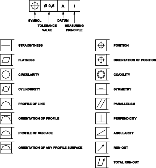
Tolerance Frame with Symbol identifications
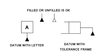
Indication of datum
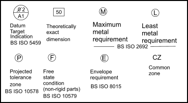
Supplimentary Symbols
Notes on supplimentary symbols are provided on webpage Geometrical Tolerancing Notes Tolerance Frame Variations The tolerance frame can be divided into two or more compartments.
When multiple datums are referenced in the tolerance box they are indicated as below:
Maximum Material Indication in Tolerance Frame The maximum material condition, when used, is indicated by a symbol placed
after the tolerance value, after the datum letter, or both.
Additional Frames- Notes If a single frame cannot convey sufficient information it is acceptable to stack additional frames and/or provide additional notes..
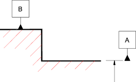
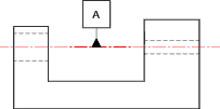
Positioning of Frames /Datum triangles The datum triangle is placed on a feature or on an extension of the outline ( but clearly separated from the dimension line) when the datum feature is the line or surface itself
The datum triangle is place on the extension of a dimension arrow when the datum feature
is the axis or medium line.
The datum can be located on the axes or median line when
Geometric Tolerancing Examples |
Links Providing information on Geometrical Tolerancing
<
|
|
