Drive_Index
Gears Gearboxes
Bevel Gears
| Introduction There are four basic types of bevel gears.
Specifications BS 545:1982..Specification for bevel gears (machine
cut)..(Obsolescent) Straight bevel gears These are gears cut from conical blanks and connect
intersecting shaft axes. The connecting shafts are
generally at 90o and sometimes one shaft drives a
bevel gear which is mounted on a through shaft resulting in two
output shafts. The point of intersection of the
shafts is called the apex and the teeth of the two gears converge
at the apex. The design of bevel gears results in
thrust forces away from the apex. With the bearing
limitations the gears have to be carefully designed to ensure
that they are not thrown out of alignment as they are
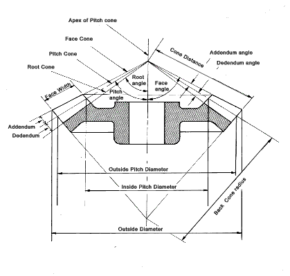
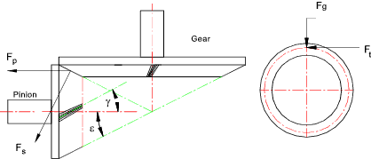
loaded. Straight Bevel Gear Terminology
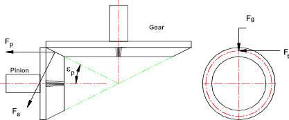
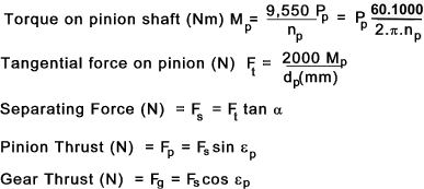
Straight Bevel Gear Force equations
Nomenclature z p = Number of teeth on pinion
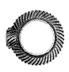
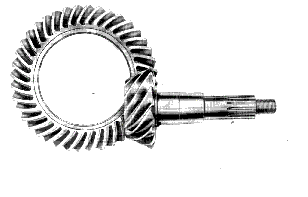
Zerol Bevel Gears The advantage of Zerol bevel gears compared to straight bevel gears is that they operate with a smooth localised point contact as opposed to a line contact enabling smoother operation with low vibration levels and higher speeds. Because there is no spiral angle and no additional developed thrust these gears can be used as direct replacements for straight bevel gears. These gears normally have a pressure angle of 20 o. The minimum number of teeth on the pinion is 14. The design of Zerol gears is relatively specialised and they are manufactured using special "Gleason" machine tools.. Spiral Bevel Gear These are produced using a spiral gear form which results in a smoother drive suitable for higher speed higher loaded applications. Again satisfactory performance of this type of gear is largely dependent upon the rigidity of the bearings and mountings.
α n = Normal Pressure
angle.. Pinion Thrust F p = F t [ (tan α n sin ε / cos γ ) ± tan g cos ε ] Note: ( + ) if helix angle is as shown and (
-) if helix angle is opposite to that shown Hypoid Bevel Gear Hypoid gears are best for the applications requiring large speed reductions with non intersecting shafts and those applications requiring smooth and quiet operation. Hypoid gears are generally used for automotive applications. The minimum number of teeth for speed ratios greater than 6 :1 is eight although 6 teeth pinions can be used for ratios below 6:1. Hypoid gears have pressure angles between 19 and 22o. The design of hypoid gears is relatively specialised and they are manufactured using special "Gleason" machine tools..
Straight Bevel Gear Strength and Durability Equations Designing bevel gears is normally done in accordance with
standards as listed under specifications above: The notes below
relate to approximate methods for estimating gear
strengths. The methods are really only useful for
first approximations and/or selection of stock gears (ref links
below). — Detailed design of bevel gears should only
be completed using the relevant standards. Books are
available providing the necessary guidance. Software
is also available making the process very easy. Bending Strength Equations The basic lewis formula for spur gear teeth is shown as follows s = F t / ( W. m. Y )
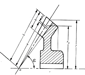
The Lewis formula is modified to provide the allowable tangential force F b based on the allowable bending Stress S b F a = S b.W. m. Y It is clear that a bevel gear does not have a uniform section or a uniform module and therefore it is necessary to start an analysis by considering an element dx..
The Lewis formula applied to the element is as follows
To obtain the allowable torque (M) transmitted by the gears multiply both sides by r xand integrate the resulting equations as shown below
The module varies along the gear teeth in proportion to the
radius from the apex along the pitch cone.
d x varies from x = (L -b) to x = L the integration can be solved as follows:
The face width is considered to be limited to 1/3 of the cone
distance when the factor b2 / (3.L2) = 1/27
is so small compared to the other factors that it can be
reasonably ignored . Then dividing by r to arrive at
the Lewis equation for the allowable bending load
The allowable bending load F b must be greater than the dynamic load which is the actual bending load calculated from the transmitted torque modified by the Barth formula as identified in the notes on spur gears i.e F b ³ F t / K v K v is given by the Barth equation for milled profile gears. K v = 6,1 / (6,1 +V ) Note: This factor is different for different gear conditions i.e
K v = ( 3.05 + V )/3.05 for cast iron, cast profile
gears. Surface Durability Equations
The gear durability equation is based on the Hertz contact stress
equation and its application to gears. F w = d p. K. Q' / cos ε p
d p = Pitch diameter measured at the back of
tooth F w ³ F t / K v |
Links to Bevel Gears
|
|
Home
Drive_Index
Gears Gearboxes
Send Comments to [email protected]
