Drive_Index
Gears Gearboxes
Differential Gears
|
Introduction A differential gear includes two coaxial gears which are connected by one or more
similar planet gears mounted on intermediate shafts.
Those shafts are fixed to a carrier. The arrangement is such that the
angular velocity of the planet gears is the average of the angular velocities of
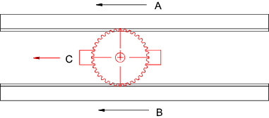
the two co-axial gears. Linear differential A linear version of the differential gear is shown below. It is clear from this diagram that the velocity of C = the average of the velocities of A & B.
Vc = VA + VB / 2
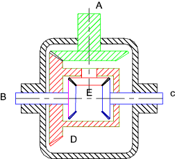
Automobile drive differential Considering the type of differential as used for car drives. In the figure below the drive shaft is connected to the gear A. This drives the case D via a bevel drive. The case rotates and drives the wheel drives B and C via the gear E. If the gear E is fixed then the wheels would rotate at the same speed as the case. As the the gear E is free to rotate the average speed of the wheels is the same as the case. Therefore if one wheel locks the second wheel would rotate at twice the speed of the case.
Power: Generally each gear mesh will have 1% - 2% loss in efficiency, so with two different meshes from the transmission shaft to each of the half shafts, the system will actually be 96% to 98% efficient. If the system is assumed to be 100% efficient; then
Drive Power A = Driven Power B + Driven Power C
Px is the power : |
Links to Differential gear design
|
|
Gears Gearboxes