Introduction
Prime movers such as Electric motors, internal combustion engines, steam engines
and turbines produce rotary motion at certain speeds and with certain torques at optimum
efficiency. The motion produced is rarely equal to the motion required to do
the necessary work and gear trains are required to translate the motion economically
at maximum efficiency.
It may be possible to use a low cost method of translating the motion e.g. a timing
belt vee belt or chain transmission system. However these methods are
limiting in their scope and are subject to regular maintenance and replacement.
The engineered gearbox generally provides the optimum solution. Many
companies provide motorised gear units with the electric motor mounted directly
onto a gearbox providing the drive conditions (torque and speed ) exactly as required
by the user. Once installed to the manufacturers instructions the only
maintenance required is regular lubrication.
Gearboxes can be engineered to allow gear ratio changes to enable output shaft speed
while keeping the input speed and torque at the same value.
The primary advantage for using a gearbox for changing speed is to enable the full
power to be transmitted at the different speeds. Electric motors and other
prime movers are rated for a maximum torque at the optimum speed. If the speed is
reduced using electronic controls the resulting developed torque is not proportionally
increased.
Gearboxes also allow the input shaft and the output shaft to be in different
directions.
Simple Drive Train Rules
1) For any pair of meshing gears the angular velocity ratio is given by
w2 /w1
= ω z1 /z2
= ω d1 / d2
w1 = Input speed (rads/s)
w2 = Output speed (rads/s)
z1 Number of teeth on input gear
z2 Number of teeth on output gear
d1 Pitch Circle Dia of the input gear
d2 Pitch Circle Dia of the output gear
The sign is - (Reversing) if both gears are external and + (Same direction)if one gear is a ring (internal gear)
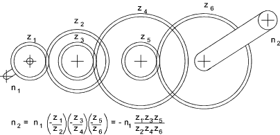
2) For a train of gear wheels the overall angular velocity ratio is given by
w2 /w1
= ω Product of teeth No's Driving gears / Product of teeth No's Driven gears
= ω Product of pitch diameters (Driving gears) / Product of pitch diameters (Driven gears)
The sign is - (Reversing) if there are an odd number of pairs of external gears

Gearbox Design Features
The design of the gearbox includes the following features..
- Input and output shaft relative positions and orientation
- Support of external forces on shafts
- Design and rigidity of casing
- Type, dimensions and strength of gears
- Method of changing speed /direction if required
- Design and strength of gear shafts
- Gearbox bearings
- Gearbox Seals
- Lubrication
- Noise and vibration
- Couplings to shaft
- Fixing /support of gearbox
- Heat dissipation
- Maintenance provisions
|
Gearbox Examples
A gearbox is loosely defined as an enclosure for housing gears. Examples of gearboxes
are numerous and some are listed below:
- Watch mechanism
- Bicycle axle gear (Sturmy Archer-3 speed) Sprocket to wheel axle -(Sturmy Archer-3 speed)
- Power tool gear units - allowing speed reduction, change and reversing
- Automobile synchromesh gearbox -5 speed + reverse - Engine to drive shafts
- Machine tool integral - Electric motor drive to spindle and travelling motions
- Wind turbine gearbox - Turbine to generator
- Steam turbine - speed reduction turbine to generator
- Marine - Gearbox - turbine /diesal prime movers to Prop shaft
- Cranes -Gearbox usind for lifting and travelling motions
|
These are all specialised applications and the notes on this page relate to gear units
manufactured as separate units for mounting in transmission systems.
The normal method of fixing an enclosed gearbox in industry is to mount it on a rigid horizontal baseplate
designed to absorb vibration. The rotary motion is transferred to the input shaft and from the output
shafts via flexible couplings. There are a number of variations as listed below
Mounting
- Foot mounted on vertical surfaces
- Foot mounted below horizontal surface
- Flange mounted onto the prime mover
- Shaft mounted with a torque arm to prevent rotation of gearbox
|
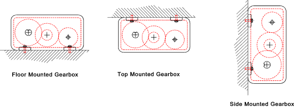
The sketches below show examples of gearboxes mounted in different ways. These are
only illustrative sketches and should not be considered as gearbox designs..


When using a gearbox in a non-standard mounting position the lubrication system
should be checked for suitability
Gearbox Casing
The large gearbox casings are generally castings from cast iron or steel.
Cast iron is a rigid material with excellent vibration damping properties.
Fabricated steel gearbox are used for small batch quantities.
Gearboxes used for the transmissions in vehicles are often made from cast aluminium
this is primarily to save weight.
The tiny gearbox units are made from a variety of materials including cast zinc alloys.
The important criteria in the gearbox casing design are listed below..
- Inclusion of safe lifting points to allow installation
- Support of the shaft bearings and hence the gear loadings;
- The transfer of the developed gear forces to supporting structure or further drive element;
- Containment of lubricant and exclusion of foreign matter;
- Providing a safety and noise barrier;
- Dissipation of the heat generated by gear friction
- Aiding testing, installation, and maintenance by containing all element in one unit;
- Providing convenient access to internals for inspection & maintainance
- Aesthetic benefits
- Enable accessible location of nameplate with all of the gear unit details
|
Gearbox shafts
A variety of shaft designs are available including the following
- Plain shaft with keyway
- Plain shaft suitable for Friction drive coupling system
- Splined shaft
- Hollow shaft with internal keyway
- Flange
|
The selection of the drive shaft system is generally based on space considerations,
on the design of the prime mover of the driven component and on the loading pattern.
A proprietary gearbox is design to best fit in with the existing drive arrangements.
Shaft Orientation
The shafts transfer of motion to and from a gearbox can be supplied in a variety
of designs some of which are listed below.
- Inline shafts .....Epi-cyclic. spur, helical, harmonic
- Parallel shafts .... spur, helical
- Shafts at angles but non intersecting....Helical, Worm, Hypoid, Spiroid gears
- Shafts at angles and intersecting... Bevel gears
|
Worm gears and bevel gears are most commonly supplied with shafts at Right angles.
| 

