Drive_Index Gear Efficiency
|
Introduction
Important Note: The efficiency of a gear system is simple calculated as the [output shaft power /Input shaft power ].100 %. The output power is the (input power - the power losses). Power losses
in gear systems are associated primarily with tooth friction and lubrication churning losses.
Churning losses are relatively independent of the nature of the gears and the gear ratios - they are primarily realated
to the peripheral speed of the gears passing through the fluid. Churning losses are difficult to calculate and
estimates based on experience are often used in initial gear design.
The frictional losses are related to the gear design,the reduction ratio,the pressure
angle, gear size, and the coefficient of friction.
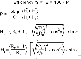
Considering a spur gear a good first approximation for average operating conditions is that the power loss at each mesh can be approximated as P% of the potential power transmitted through the mesh. The efficiency is therefore..
Clarification of formula terms.
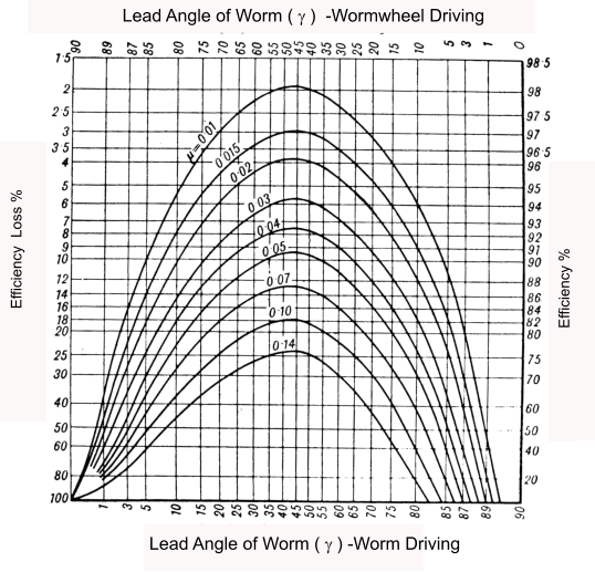
The theoretical efficiency of a worm gear is provided on page worm gears and is shown again below as. The graph below shows a worm gear efficiencies plotted against the lead angle for different coefficient of friction μ = 0,04 vs-0,25 vs = sliding velocity (m/s)
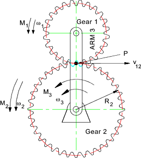
Epicyclic Gears Consider the two meshing gears below which are part of an epicyclic gear train. This is provided as and example of a typical component in an epicyclic gear. The two gears and the arms are rotating as shown .
Now it the arm was stationary the contact point P would have a instantaneous velocity = -ω2 R2. (velocities to the right are positive ). Now if the whole system was rotating as a rigid assembly with the velocity of the arm the instantaneous velocity -ω3 R2. Combining these two motions together, the linear velocity of the tooth engagement (gear 2 -> gear 1)is therefore v12 = - ( ω2 R2 - ω3 R2) = - (ω2 - ω 3)R 2 Now the magnitude of the transmitted tangential force F12 x the tooth engagement velocity v12 is called the potential power and the power loss due to tooth friction is proportional to this power. Generally for spur gears ( and helical gears) it is sufficient to estimate the power loss as 1% of the potential power. For more accurate estimations the equations above can be used. P = 0,01 F12v12 The potential power is not the actual power but is the but is the power
transmitted by the same gears operating on fixed centres at angular velocities of
( ω2 - ω3 ) for gear 2 and
( ω1 - ω3 ) for gear 2.
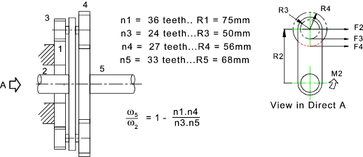
Now in cases where the arm is rotating faster than the gear the potential power can be greater than the actual power and the losses proportionally greater. Example Epicyclic Gear efficiency calculation.Consider the epicyclic gear chain shown below. The input speed = 250 RPM (ACW) and the input torque = 2.5 Nm
ω2 = (250.2.π)/60 = 26,18rads/s. and
ω1 = 0
For the gear mesh between gear 3 and the fixed sun 2 the velocity of tooth engagement is calculated
by the product of the angular velocity of the arm 2 at pitch radius of R2. = ω2R1 = 26,18.0,075 = 1,96m/s
The velocity of tooth engagement between gear (4) and gear (5) = |
Links to Gear Efficiency
|
|
Drive_Index


