Introduction
A worm gear is used when a large speed reduction ratio is required between
crossed axis shafts which do not intersect. A basic helical gear can be used but the power
which can be transmitted is low. A worm drive consists of a large diameter
worm wheel with a worm screw meshing with teeth on the periphery of the worm wheel.
The worm is similar to a screw and the worm wheel is similar to a section of a nut.
As the worm is rotated the wormwheel is caused to rotate due to the screw like action
of the worm. The size of the worm gearset is generally based on the
centre distance between the worm and the wormwheel.
If the worm gears are machined basically as crossed helical gears the result is a highly stress
point contact gear. However normally the wormwheel is cut with a concave as opposed to a straight
width. This is called a single envelope worm gearset. If the worm is machined with
a concave profile to effectively wrap around the wormwheel the gearset is called a double enveloping worm gearset
and has the highest power capacity for the size. Single enveloping gearsets require accurate alignment of
the worm-wheel to ensure full line tooth contact. Double enveloping gearsets require accurate
alignment of both the worm and the wormwheel to obtain maximum face contact.
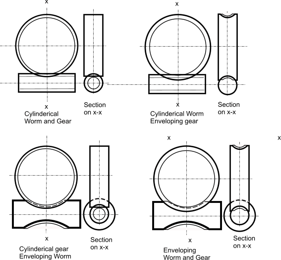
Diagram showing the different worm gear options available.
The double enveloping (double throat/double globoid ) option is the most difficult to manufacture and
set up. However this option has the highest load capacity, near zero backlash capability, highest accuracy and extended life capability.
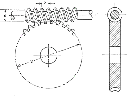
A more detailed view showing a cylinderical worm and an enveloping gear. The worm is shown with the worm above the wormwheel. The gearset can also be arranged with the
worm below the wormwheel. Other alignments are used less frequently.
Nomenclature
As can be seen in the above view a section through the axis of the worm and the centre
of the gear shows that , at this plane, the meshing teeth and thread section is similar
to a spur gear and has the same features
αn = Normal pressure angle = 20o as standard
γ = Worm lead angle = (180 /π ) tan-1 (z 1 / q)(deg)
..Note: for α n= 20o γ should be less than 25o
b a = Effective face width of worm wheel. About 2.m √ (q +1) (mm)
b l = Length of worm wheel. About 14.m. (mm)
c = clearance c min = 0,2.m cos γ , c max = 0,25.m cos γ (mm)
d 1 = Ref dia of worm (Pitch dia of worm (m)) = q.m (mm)
d a.1 = Tip diameter of worm = d 1 + 2.h a.1 (mm)
d 2 = Ref dia of worm wheel (Pitch dia of wormwheel) =( p x.z/π ) = 2.a - d 1 (mm)
d a.2 = Tip dia worm wheel (mm)
h a.1 = Worm Thread addendum = m (mm)
h f.1 = Worm Thread dedendum , min = m.(2,2 cos γ - 1 ) , max = m.(2,25 cos γ - 1 )(mm)
m = Axial module = p x /π (mm)
m n = Normal module = m cos γ(mm)
M 1 = Worm torque (Nm)
M 2 = Worm wheel torque (Nm)
n 1 = Rotational speed of worm (revs /min)
n 2 = Rotational speed of wormwheel (revs /min)
p x = Axial pitch of of worm threads and circular pitch of wheel teeth ..the pitch between adjacent threads = π. m. (mm)
p n = Normal pitch of of worm threads and gear teeth (m)
q = Worm diameter factor = d 1 / m - (Allows module to be applied to worm ) selected from
(6 6,5 7 7,5 8 8,5
9 10 11 12 13 14 17 20 )
p z = Lead of worm = p x. z 1 (mm)..
Distance the thread advances in one rev'n of the worm.
For a 2-start worm the lead = 2 . p x
R g = Reduction Ratio
μ = coefficient of friction
η= Efficiency
Vs = Worm-gear sliding velocity ( m/s)
z 1 = Number of threads (starts) on worm
z 2 = Number of teeth on wormwheel
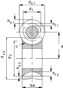
Worm gear design parameters
Worm gears provide a normal single reduction range of 5:1 to 75-1. The pitch line
velocity is ideally up to 30 m/s. The efficiency of a worm gear ranges from 98% for
the lowest ratios to 20% for the highest ratios. As the frictional heat generation
is generally high the worm box must be designed disperse heat to the surroundings and lubrication is
an essential requirement. Worm gears are quiet in operation. Worm gears
at the higher ratios are inherently self locking - the worm can drive the gear but the gear cannot
drive the worm. A worm gear can provide a 50:1 speed reduction but not
a 1:50 speed increase....(In practice a worm should not be used a braking device for
safety linked systems e.g hoists. . Some material and operating conditions can result
in a wormgear backsliding )
The worm gear action is a sliding action which results in significant frictional losses.
The ideal combination of gear materials is for a case hardened alloy steel worm (ground finished) with a phosphor bronze gear. Other
combinations are used for gears with comparatively light loads.
Specifications
BS721 Pt2 1983 Specification for worm gearing � Metric units.
This standard is current (2004) and provides information on tooth form, dimensions
of gearing, tolerances for four classes of gears according to function and accuracy,
calculation of load capacity and information to be given on drawings.
Worm Gear Designation
Very simply a pair of worm gears can be defined by designation of the number of threads in the worm
,the number of teeth on the wormwheel, the diameter factor and the axial module i.e z1,z2, q, m
.
This information together with the centre distance ( a ) is enough to enable calculation of and
any dimension of a worm gear using the formulea available.
Worm teeth Profile
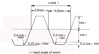
The sketch below shows the normal (not axial) worm tooth profile as indicated in BS 721-2 for unit axial module (m = 1mm)
other module teeth are in proportion e.g. 2mm module teeth are 2 times larger
Typical axial modules values (m) used for worm gears are
0,5 0,6 0,8 1,0 1,25 1,6 2,0
2,5 3,15 4,0 5,0 6,3 8,0 10,0
12,5 16,0 20,0 25,0 32,0 40,0 50,0
Materials used for gears
| | |
| Material | Notes | applications |
| Worm |
| Acetal / Nylon | Low Cost, low duty | Toys, domestic appliances, instruments |
| Cast Iron | Excellent machinability, medium friction. | Used infrequently in modern machinery |
| Carbon Steel | Low cost, reasonable strength | Power gears with medium rating. |
| Hardened Steel | High strength, good durability | Power gears with high rating for extended life |
| Wormwheel |
| Acetal /Nylon | Low Cost, low duty | Toys, domestic appliances, instruments |
| Phos Bronze | Reasonable strength, low friction and good compatibility with steel | Normal material for worm gears with reasonable efficiency |
| Cast Iron | Excellent machinability, medium friction. | Used infrequently in modern machinery |
Backlash / quality Grades
A worm gear set normally includes some backlash during normal manufacture to allow for expansion
of the gear wheel when operating at elevated temperaturs. The backlash is controlled by adusting the gear wheel
tooth thickness.
BS 721 includes a table of backlash limits related to the accuracy grade. The standard
lists 5 accuracy grades.
AGMA and DIN provide a similar grading system
- Grade 1 relates to critical applications where minimum backlash is required i.e instruments /metering
- Grade 2 relates to precision drives such as machine tools
- Grade 3,4,5 relates to industrial drives with working temperatures of about 120o C
|
Design of a Worm Gear
The following notes relate to the principles in BS 721-2
Method associated with AGMA are shown below..
Initial sizing of worm gear.. (Mechanical)
1) Initial information generally Torque required (Nm), Input speed(rpm), Output speed (rpm).
2) Select Materials for worm and wormwheel.
3) Calculate Ratio (R g)
4) Estimate a = Center distance (mm)
5) Set z 1 = Nearest number to (7 + 2,4 SQRT (a) ) /R g
6) Set z 2 = Next number < R g . z 1
7) Using the value of estimated centre distance (a) and No of gear teeth ( z 2 ) obtain a value for q from the table below. (q -value selection)
8) d 1 = q.m (select) ..
9) d 2 = 2.a - d 1
10) Select a wormwheel face width b a (minimum =2*m*SQRT(q+1))
11) Calculate the permissible output torques for strength (M b_1 and wear M c_1 )
12) Apply the relevent duty factors to the allowable torque and the actual torque
13) Compare the actual values to the permissible values and repeat process if necessary
14) Determine the friction coefficient and calculate the efficiency.
15) Calculate the Power out and the power in and the input torque
16) Complete design of gearbox including design of shafts, lubrication, and casing ensuring
sufficient heat transfer area to remove waste heat.
Initial sizing of worm gear.. (Thermal)
Worm gears are often limited not by the strength of the teeth but by the heat generated
by the low efficiency. It is necessary therefore to determine the heat generated by
the gears = (Input power - Output power). The worm gearbox must have lubricant to remove
the heat from the teeth in contact and sufficient area on the external surfaces to distibute
the generated heat to the local environment. This requires completing an approximate heat
transfer calculation. If the heat lost to the environment is insufficient then the gears should
be adjusted (more starts, larger gears) or the box geometry should be adjusted, or the worm shaft
could include a fan to induced forced air flow heat loss.
Formulae
The reduction ratio of a worm gear ( R g )
R g = z 2 / z 1
eg a 30 tooth wheel meshing with a 2 start worm has a reduction of 15
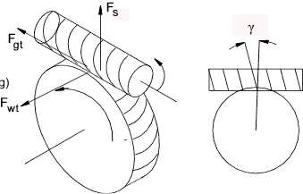
Tangential force on worm ( F wt )= axial force on wormwheel
F wt = F ga = 2.M 1 / d 1
Axial force on worm ( F wa ) = Tangential force on gear

Output torque ( M 2 ) = Tangential force on wormwheel * Wormwheel reference diameter /2
M 2 = F gt* d 2 / 2
Relationship between the Worm Tangential Force F wt and the Gear Tangential force F gt

Relationship between the output torque M 2and the input torque M 1
M 2 = ( M 1. d 2 / d 1 ).[ (cos α n - μ tan γ ) /
(cos α n . tan (γ + μ) ) ]
Separating Force on worm-gearwheel ( F s )

Sliding velocity ( V s )...(m/s)
V s (m/s ) = 0,00005236. d 1. n 1 sec γ
= 0,00005235.m.n (z 12 + q 2 ) 1/2 Peripheral velocity of wormwheel ( V p) (m/s)
V p = 0,00005236,d 2. n 2
Friction Coefficient
Note: The values of the coeffient of friction as provided in the table below are based on the use of phosphor bronze wormwheels
and case hardended , ground and polished steel worms , lubricated by a mineral oil having a viscosity of between 60cSt, and 130cSt at 60 deg.C .
Cast Iron and Phosphor Bronze .. Table x 1,15
Cast Iron and Cast Iron.. Table x 1,33
Quenched Steel and Aluminum Alloy..Table x 1,33
Steel and Steel..Table x 2
Friction coefficients - For Case Hardened Steel Worm / Phos Bros Wheel
| Sliding Speed |
Friction Coefficient |
Sliding Speed |
Friction Coefficient |
| m/s |
μ |
m/s |
μ |
| |
|
|
|
| 0 |
0,145 |
1,5 |
0,038 |
| 0,001 |
0,12 |
2 |
0,033 |
| 0,01 |
0,11 |
5 |
0,023 |
| 0,05 |
0,09 |
8 |
0,02 |
| 0,1 |
0,08 |
10 |
0,018 |
| 0,2 |
0,07 |
15 |
0,017 |
| 0,5 |
0,055 |
20 |
0,016 |
| 1 |
0,044 |
30 |
0,016 |
Efficiency of Worm Gear
The efficiency of the worm gear is determined by dividing the output Torque M2 with friction = μ by the output torque with zero losses i.e μ
= 0
First cancelling [( M 1. d 2 / d 1 ) / M 1. d 2 / d 1 ) ] = 1
Denominator = [(cos α n / (cos α n . tan γ ] = cot γ
η = [(cos α n - μ tan γ ) /
(cos α n . tan γ + μ ) ] /
cot γ = [(cos α n - μ .tan γ ) /
(cos α n + μ .cot γ )]
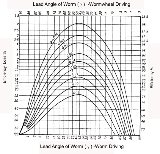
Graph showing worm gear efficiency related to gear lead angle ( γ )
Self Locking
Referring to the above graph , When the gear wheel is driving the curve points intersecting the
zero efficiency line identify when the worm drive is self locking i.e the gear wheel cannot drive to worm.
It is the moment when gearing cannot be moved using even the highest possible torque acting on the worm gear.
The self-locking limit occurs when the worm lead angle ( γ ) equals atan (μ). (2o to 8o )
It is often considered that the static coefficient of friction is most relevant as the gear cannot be started. However
in practice it is safer to use the, lower, dynamic coefficient of friction as this comes into play if the gear set is subject
to vibration.
Worm Design /Gear Wear / Strength Equations to BS721
Note: For designing worm gears to AGMA codes AGMA method of Designing Worm Gears
The information below relates to BS721 Pt2 1983 Specification for worm gearing �
Metric units. BS721 provides average design values reflecting the experience
of specialist gear manufacturers. The methods have been refined by addition of various application
and duty factors as used. Generally wear is the critical factor..
Permissible Load for Strength
The permissible torque (M in Nm) on the gear teeth is obtained by use of the equation
M b = 0,0018 X b.2σ bm.2. m. l f.2. d 2.
( example 87,1 Nm = 0,0018 x 0,48 x 63 x 20 x 80 )
X b.2 = speed factor for bending (Worm wheel ).. See Below
σ bm.2 = Bending stress factor for Worm wheel.. See Table below
l f.2 = length of root of Worm Wheel tooth
d 2 = Reference diameter of worm wheel
m = axial module
γ = Lead angle
Permissible Torque for Wear
The permissible torque (M in Nm) on the gear teeth is obtained by use of the equation
M c = 0,00191 X c.2σ cm.2.Z. d 21,8. m
( example 33,42 Nm = 0,00191 x 0,3234 x 6,7 x 1,5157 x 801,8 x 2 )
X c.2 = Speed factor for wear ( Worm wheel )
σ cm.2 = Surface stress factor for Worm wheel
Z = Zone factor.
Length of root of worm wheel tooth
Radius of the root = R r= d 1 /2 + h ha,1 (= m) + c(= 0,25.m.cos γ )
R r= d 1 /2 + m(1 +0,25 cosγ)
l f.2 = 2.R r.sin-1 (2.R r / b a)
Note: angle from sin-1(function) is in radians...
Speed Factor for Bending
This is a metric conversion from an imperial formula..
X b.2 = speed factor for bending = 0,521(V) -0,2
V= Pitch circle velocity =0,00005236*d 2.n 2 (m/s)
The table below is derived from a graph in BS 721. I cannot
see how this works as a small worm has a smaller diameter compared
to a large worm and a lower speed which is not reflected in using the
RPM.
Table of speed factors for bending
| RPM (n2) |
X b.2 |
RPM (n2) |
X b.2 |
| 1 |
0,62 |
600 |
0,3 |
| 10 |
0,56 |
1000 |
0,27 |
| 20 |
0,52 |
2000 |
0,23 |
| 60 |
0,44 |
4000 |
0,18 |
| 100 |
0,42 |
6000 |
0,16 |
| 200 |
0,37 |
8000 |
0,14 |
| 400 |
0,33 |
10000 |
0,13 |
Additional factors
The formula for the acceptable torque for wear should be modified to allow
additional factors which affect the Allowable torque M c
M c2 = M c. Z L. Z M.Z R / K C
The torque on the wormwheel as calculated using the duty requirements (M e) must be less
than the acceptable torque M c2 for a duty of 27000 hours with uniform
loading.
For loading other than this then M e should be modified as follows
M e2 = M e. K S* K H
Thus
uniform load < 27000 hours (10 years) M e ≤ M c2
Other conditions M e2 ≤ M c2
Factors used in equations
Lubrication (Z L)..
Z L = 1 if correct oil with anti-scoring additive else a lower value should be selected
Lubricant (Z M)..
Z L = 1 for Oil bath lubrication at V s < 10 m /s
Z L = 0,815 Oil bath lubrication at 10 m/s < V s < 14 m /s
Z L = 1 Forced circulation lubrication
Surface roughness (Z R ) ..
Z R = 1 if Worm Surface Texture < 3μ m and Wormwheel < 12 μ m
else use less than 1
Tooth contact factor (K C
This relates to the quality and rigidity of gears . Use 1 for first estimate
K C = 1 For grade A gears with > 40% height and > 50% width contact
= 1,3 - 1,4 For grade A gears with > 30% height and > 35% width contact
= 1,5-1,7 For grade A gears with > 20% height and > 20% width contact
Starting factor (K S) ..
K S =1 for < 2 Starts per hour
=1,07 for 2- 5 Starts per hour
=1,13 for 5-10 Starts per hour
=1,18 more than 10 Starts per hour
Time / Duty factor (K H) ..
K H for 27000 hours life (10 years) with uniform driver and driven loads
For other conditions see table below
Tables for use with BS 721 equations
Speed Factors
X c.2 = K V .K R
Note: This table is not based on the graph in BS 721-2 (figure 7) it is based
on another more easy to follow graph. At low values of sliding velocity
and RPM it agrees closely with BS 721. At higher speed velocities it gives a lower
value (e.g at 20m/s -600 RPM the value from this table for X c.2 is about
80% of the value in BS 721-2
Table of Worm Gear Speed Factors
Note -sliding speed = Vs and Rotating speed = n2 (Wormwheel)
Sliding speed
|
K V | Rotating Speed
|
K R |
| m/s |
|
rpm |
|
| 0 |
1 |
0,5 |
0,98 |
| 0,1 |
0,75 |
1 |
0,96 |
| 0,2 |
0,68 |
2 |
0,92 |
| 0,5 |
0,6 |
10 |
0,8 |
| 1 |
0,55 |
20 |
0,73 |
| 2 |
0,5 |
50 |
0,63 |
| 5 |
0,42 |
100 |
0,55 |
| 10 |
0,34 |
200 |
0,46 |
| 20 |
0,24 |
500 |
0,35 |
| 30 |
0,16 |
600 |
0,33 |
Stress Factors
Table of Worm Gear Stress Factors
| |
Other metal
(Worm) |
P.B. |
C.I. |
0,4%
C.Steel |
0,55%
C.Steel |
C.Steel
Case. H'd |
Metal
(Wormwheel) |
Bending
(σbm ) |
Wear ( σ cm ) |
MPa |
MPa |
Phosphor Bronze
Centrifugal cast |
69 |
|
8,3 |
8,3 |
9,0 |
15,2 |
Phosphor Bronze
Sand Cast Chilled |
63 |
|
6,2 |
6,2 |
6,9 |
12,4 |
Phosphor Bronze
Sand Cast |
49 |
|
4,6 |
4,6 |
5,3 |
10,3 |
| Grey Cast Iron |
40 |
6,2 |
4,1 |
4,1 |
4,1 |
5,2 |
| 0,4% Carbon steel |
138 |
10,7 |
6,9 |
|
|
|
| 0,55% Carbon steel |
173 |
15,2 |
8,3 |
|
|
|
Carbon Steel
(Case hardened) |
276 |
48,3 |
30,3 |
|
|
15,2 |
Zone Factor (Z)
If b a < 2,3 (q +1)1/2 Then Z = (Basic Zone factor ) . b a /2 (q +1)1/2
If b a > 2,3 (q +1)1/2 Then Z = (Basic Zone factor ) .1,15
Table of Basic Zone Factors
| |
q |
| z1 |
6 |
6,5 |
7 |
7,5 |
8 |
8,5 |
9 |
9,5 |
10 |
11 |
12 |
13 |
14 |
17 |
20 |
| 1 |
1,045 |
1,048 |
1,052 |
1,065 |
1,084 |
1,107 |
1,128 |
1,137 |
1,143 |
1,16 |
1,202 |
1,26 |
1,318 |
1,402 |
1,508 |
| 2 |
0,991 |
1,028 |
1,055 |
1,099 |
1,144 |
1,183 |
1,214 |
1,223 |
1,231 |
1,25 |
1,28 |
1,32 |
1,36 |
1,447 |
1,575 |
| 3 |
0,822 |
0,89 |
0,989 |
1,109 |
1,209 |
1,26 |
1,305 |
1,333 |
1,35 |
1,365 |
1,393 |
1,422 |
1,442 |
1,532 |
1,674 |
| 4 |
0,826 |
0,83 |
0,981 |
1,098 |
1,204 |
1,701 |
1,38 |
1,428 |
1,46 |
1,49 |
1,515 |
1,545 |
1,57 |
1,666 |
1,798 |
| 5 |
0,947 |
0,991 |
1,05 |
1,122 |
1,216 |
1,315 |
1,417 |
1,49 |
1,55 |
1,61 |
1,632* |
1,652 |
1,675 |
1,765 |
1,886 |
| 6 |
1,131 |
1,145 |
1,172 |
1,22 |
1,287 |
1,35 |
1,438 |
1,521 |
1,588 |
1,625 |
1,694 |
1,714 |
1,733 |
1,818 |
1,928 |
| 7 |
|
|
1,316 |
1,34 |
1,37 |
1,405 |
1,452 |
1,54 |
1,614 |
1,704 |
1,725 |
1,74 |
1,76 |
1,846 |
1,98 |
| 8 |
|
|
|
|
1,437 |
1,462 |
1,5 |
1,557 |
1,623 |
1,715 |
1,738 |
1,753 |
1,778 |
1,868 |
1,96 |
| 9 |
|
|
|
|
|
|
1573 |
1,604 |
1,648 |
1,72 |
1,743 |
1,767 |
1,79 |
1,88 |
1,97 |
| 10 |
|
|
|
|
|
|
|
|
1,68 |
1,728 |
1,748 |
1,773 |
1,798 |
1,888 |
1,98 |
| 11 |
|
|
|
|
|
|
|
|
|
1,732 |
1,753 |
1,777 |
1,802 |
1,892 |
1,987 |
| 12 |
|
|
|
|
|
|
|
|
|
|
1,76 |
1,78 |
1,806 |
1,895 |
1,992 |
| 13 |
|
|
|
|
|
|
|
|
|
|
|
1,784 |
1,806 |
1,898 |
1,998 |
| 14 |
|
|
|
|
|
|
|
|
|
|
|
|
1,811 |
1,9 |
2 |
Duty Factor
Duty - time Factor K H
| Impact from Prime mover |
Expected life
hours |
K H |
| Impact From Load |
| Uniform Load |
Medium Impact |
Strong impact |
Uniform Load
Motor Turbine Hydraulic motor | 1500 |
0,8 |
0,9 |
1 |
| 5000 |
0,9 |
1 |
1,25 |
| 27000 |
1 |
1,25 |
1,5 |
| 60000 |
1,25 |
1,5 |
1,75 |
Light impact
multi-cylinder engine |
1500 |
0,9 |
1 |
1,25 |
| 5000 |
1 |
1,25 |
1,5 |
| 27000 |
1,25 |
1,5 |
1,75 |
| 60000 |
1,5 |
1,75 |
2 |
Medium Impact
Single cylinder engine |
1500 |
1 |
1,25 |
1,5 |
| 5000 |
1,25 |
1,5 |
1,75 |
| 27000 |
1,5 |
1,75 |
2 |
| 60000 |
1,75 |
2 |
2,25 |
Worm q value selection
The table below allows selection of q value which provides a reasonably
efficient worm design. The recommended centre distance
value "a" (mm)is listed for
each q value against a range of z 2 (teeth number values).
The table has been produced by reference to the relevant plot in BS 721
Example
If the number of teeth on the gear is selected as 45 and the centre distance is 300 mm
then a q value for the worm would be about 7.5
Important note: This table provides reasonable values for all worm speeds. However at worm speeds
below 300 rpm a separate plot is provided in BS721 which produces more accurate q values. At these
lower speeds the resulting q values are approximately 1.5 higher than the values from this table. The above example
at less than 300rpm should be increased to about 9
Table of Center distances "a" relating to q values and Number of teeth on Worm gear z 2
| Number of Teeth On Worm Gear (z 2) |
| q | 20 |
25 |
30 |
35 |
40 |
45 |
50 |
55 |
60 |
65 |
70 |
75 |
80 |
| 6 | 150 |
250 |
380 |
520 |
700 |
|
|
|
|
|
|
|
|
| 6.5 | 100 |
150 |
250 |
350 |
480 |
660 |
|
|
|
|
|
|
|
| 7 | 70 |
110 |
170 |
250 |
350 |
470 |
620 |
700 |
|
|
|
|
|
| 7.5 | 50 |
80 |
120 |
180 |
240 |
330 |
420 |
550 |
670 |
|
|
|
|
| 8 | 25 |
50 |
80 |
120 |
180 |
230 |
300 |
380 |
470 |
570 |
700 |
|
|
| 8.5 | |
28 |
90 |
130 |
130 |
180 |
220 |
280 |
350 |
420 |
500 |
600 |
700 |
| 9 | |
|
40 |
70 |
100 |
130 |
170 |
220 |
280 |
330 |
400 |
450 |
520 |
| 9.5 | |
|
25 |
50 |
70 |
100 |
120 |
150 |
200 |
230 |
300 |
350 |
400 |
| 10 | |
|
|
26 |
55 |
80 |
100 |
130 |
160 |
200 |
230 |
270 |
320 |
| 11 | |
|
|
25 |
28 |
55 |
75 |
100 |
130 |
150 |
180 |
220 |
250 |
| 12 | |
|
|
|
|
28 |
45 |
52 |
80 |
100 |
130 |
150 |
100 |
| 13 | |
|
|
|
|
|
|
27 |
45 |
52 |
75 |
90 |
105 |
AGMA method of Designing Worm Gears
The AGMA method is provided here because it is relatively easy to use and convenient-
AGMA is all imperial and so I have used conversion values so all calculations can be completed
in metric units..
Good proportions indicate that for a centre to centre distance = C the mean worm dia d 1 is within the range
Imperial (inches)
( C 0,875 / 3 ) ≤ d 1 ≤ ( C 0,875 / 1,6 )
Metric ( mm)
( C 0,875 / 2 ) ≤ d 1 ≤ ( C 0,875 / 1,07 )
The acceptable tangential load (W t) all
(W t) all = C s. d 20,8 .b a .C m .C v . (0,0132) (N)
The formula will result in a life of over 25000 hours with a case hardened alloy steel worm and a phosphor bronze wheel
C s = Materials factor
b a = Effective face width of gearwheel = actual face width. but not to exceed 0,67 . d 1
C m = Ratio factor
C v = Velocity factor
Modified Lewis equation for stress induced in worm gear teeth .
σ a = W t / ( p n. b a. y )(N)
W t = Worm gear tangential Force (N)
y = 0,125 for a normal pressure angle α n = 20o
The friction force = W f
W f = f.W t / (. cos φ n ) (N)
γ = worm lead angle at mean diameter
α n = normal pressure angle
The sliding velocity = V s
V s = π .n 1. d 1 / (60,000 )
d 1 = mean dia of worm (mm)
n 1 = rotational speed of worm (revs/min)
The torque generated γ at the worm gear = M b (Nm)
T G = W t .d 1 / 2000
The required friction heat loss from the worm gearbox
H loss
= P in ( 1 - η )
η = gear efficiency as above.
C s values
C s = 270 + 0,0063(C )3... for C ≤ 76mm
....Else
C s (Sand cast gears ) = 1000 for d 1 ≤ 64 mm ...else... 1860 - 477 log (d 1 )
C s (Chilled cast gears ) = 1000 for d 1 ≤ 200 mm ...else ... 2052 -456 log (d 1 )
C s (Centrifugally cast gears ) = 1000 for d 1 ≤ 635 mm ...else ... 1503 - 180 log (d 1 )
C m values
NG = Number of teeth on worm gear.
NW = Number of starts on worm gear.
mG = gear ration = NG /NW

C v values
C v (V s > 3,56 m/s )
= 0,659 exp (-0,2167 V s )
C v (3,56 m/s ≤ V s < 15,24 m/s )
= 0,652 (V s) -0,571 )
C v (V s > 15,24 m/s )
= 1,098.( V s ) -0,774 )
f values
f (V s = 0)
= 0,15
f (0 < V s ≤ 0,06 m/s )
= 0,124 exp (-2,234 ( V s ) 0,645
f (V s > 0,06 m/s )
= 0,103 exp (-1,1855 ( V s ) ) 0,450 ) +0,012
|


