Introduction
The notes below describe briefly how gear teeth are formed.
The performance, life , vibration and noise levels of a gear set is directly related to the machining process ,
heat treatment, and finishing of gear teeth. The process involve include the following
|
Gear Blank Production
Each of the processes below has cost, material size, accuracy, strength, operating life advantages and selection of the primary
forming process is very important.
- Sand Casting
- Fabrication
- Forging
- Shell Molding
- Investment Casting
- Permanent Mold Casting
- Die Casting
- Centrifugal Casting
- Powder matallurgy
- Extrusion
- Injection Moulding
- Pressing/ Stamping
Gear Teeth forming Processes
- Shaping
- Milling
- Hobbing
- Cold Forming/ rolling
Gear Teeth finishing Processes
Gears running a high speeds, transmitting large forces, and requiring quiet smooth running conditions are often finished
using one of the following operations.
- Shaving
- Burnishing
- Grinding
- Lapping
- Honing
The last three options are generally considered for finishing gear teeth which have been heat treated to increase the surface
hardness of the teeth.
Heat Treatment
The life and strength of a gear can be greatly improved by heat treatmet. heat Treatment process include
- Hardening and tempering
- Surface Hardening
|
Milling
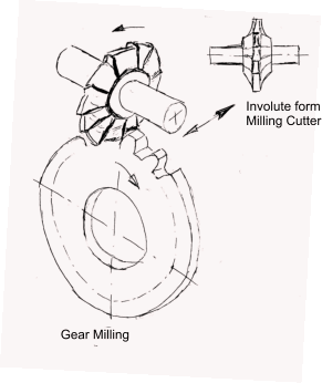
An involute form milling cutter with teeth shaped which conform to the tooth space are used to
cut involute gear teeth. This is generally completed on a horizontal milling machine
This process has a theoretical disadvantage that the tooth space profile is clearly different for gears having
different modules and different number of teeth.
This limitation is such that, for each module, by allowing some innaccuracy of form, about eight cutters are
needed for the whole range for gear teeth from 10 teeth to the
rack form. Milling is limited to making single gears for prototype or very
small batches of gears as it is a very slow and uneconomical method of production.
The milling cutter form is is machined so that it will cut the desired gear tooth space. The cutter is then driven across across the gear blank repeatedly to cut out a space. The the gear is rotated
through one circular gear pitch and the next tooth space is cut. this process is repeated until all of the teeth have been formed.
. The depth of cut into the gear blank depends on the cutter strength, set-up rigidity and machineability of the gear blank material.

Shaping
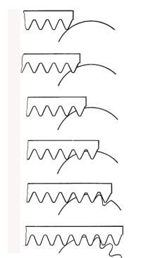
Gear teeth msy be generated using a reciprocating cutter which is of a rack form or a rotating pinion form. The process
involving the rack shaped cutter is shown below. This process is used for producing spur gears and helical gears.
The rack cutter is reciprocated across the blank-face . After each cut the rack cutter a is moved a small distance along the line of teeth and the blank
is rotated through a small angle. This is repeated until the end of the rack is reached, at which point the rack and blank have to be repositioned.
The machining process is often used for cutting very large gears
|

| 
|
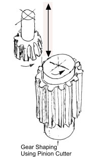
Gear shaping using a circular pinion-shaped cutter with the necessary rake angles to cut the teeth
is generally faster than using the rack form of cutter. Both the gear blank and cutter are set
in a vertical plane and rotated such as that the two are like gears in mesh. Gear cutter shaping is faster than using a rack because the cutting process is continuous and the cutter does not have to be stepped back.
Gear shaping using pinion shaped teeth can be used to produce external and internal gears and splines. The disadvantage of this method
is that the generated gear profile is directly dependent of the tooth profile any error on any tooth of the cutter is directly transferred to
the gear being cut.
Hobbing
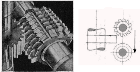
The hob is simply a rotating cutting tool that is shaped like a worm. The teeth have straight sides . However the hob axis
must be rotated through the lead angle in order to cut spur-gear teeth .
The hob is basically a straight cylindrical tool around which a thread with the same cross
section as the rack tooth has been helically wound. Both the hob and the blank are rotated at the
correct angular velocity ratio. The hob is then slowly fed across the face of the blank
until all of the teeth have been producted. The hob is then rotated with the gear blank fed onto
the hob according to the depth of cut. The helix pattern of hob as it rotates is the same as that
of the rack moving laterally.
This is the most productive of all the gear production processes. However, it
can only be used for producing spur gears and worm gears.
It cannot be used to cut internal gears and it cannot work up a shoulder.

Finishing Processes
Gear Shaving
Shaving improves gear tooth finish where the cutting process has not provided the required standard. Shaving only cuts of minute amounts
of metal bringing the a the tooth profile to within 6,5 μm. However the preceding process
must result in teeth which have small errors only in pitch, profile and concentricity. This process cannot be completed if the gear teeth
have been hardened.
The process is ideal for automative gearbox gears after hobbing and before hardening.
The shaving process involves meshing the gear with a gear shaped cutter which has
serrations across the flank of the teeth. The serrations forming the cutting edges. For a spur gear the cutter is
a helical gear and for a helical gear the cutter is a spur gear. The cutter axis is mounted at an angle to the axis of the gear.
There are various shaving actions : for traverse shaving - the shaving cutter drives the gear which reciprocates in the direction of its own axis.
Burnishing
This is cold working process accomplished by rolling the gear in contact and under
pressure with a number of hardened burnishing gears. The hardened burnishing gears have slightly oversize
teeth. The gear is run in mesh with the burnishing gears until the surface is smooth. This process
, as for shaving, cannot be carriered out if the gear is hardened.
Grinding
Heat-treated gears can be finished either by grinding when the high accuracy associated with
profile grinding is required, it is the only process to be used.
By grinding, teeth can be finished either by generation or by forming. With generation the work
is made to roll in contact with a flat faced rotating grinding wheel, which corresponds to the face of the imaginary
rack meshing with the gear. One side of tooth is ground at a time.
With forming the grinding wheel is given the shape as formed by space between two adjacent teeth and
both flanks are finished together.
,Both give equally accurate results The second method (Forming) is quicker. The process although producing accurate gears is time consuming and results
in surface scatches or ridges which may have to be removed by lapping
This process of gear finishing is not often used as the shaving process is quite satisfactory and cheaper
than gear-grinding.
Lapping
This process of gear finishing is accomplished by having the gear in
contact with one or more cast iron lap gears of true shape. The work is mounted between centers and
is slowly driven by the rear lap. The teeth of the gear and lap are made to slide (reciprocate) axially
relative to each other so that the whole surface of the teeth is abraided equally. .
A fine abrasive is used with light oil to assist cutting action. The process generally only takes a few minutes
(10 to 15).
Automative gearbox gears finished before case hardening by shaving are usually finally lapped
Honing
Gear honing (Shave Grinding). is a finishing process that can be applied to external and
internal spur or helical gears. The process involves running the workpiece in mesh with a high quality
gear honing tool/wheel with suitable abrasives . The honing tool is like a gear driving the
workpiece at high speed (upto 30 m/m) while oscillating such that the teeth slide against the workpiece teeth. The honing tool is traversed back and forth
across the gear face and the direction of rotation of the honing tool is reversed at the end of each stroke
General-purpose honing tools are made in variety of resin and abrasive mixes for gears that have been
shaved and heat-treated.
With this process finishes of 0,75 μm. are easily achieved and 0,075μm. are possible.
|