Introduction
When designing a gearbox it is necessary to consider the need to remove the heat
that is generated inside the gearbox due to the mechanical inefficiency of the gear
action. This is not too important for the efficient gears such as spur
gears and helical gears.
Generally the surface area of the enclosing box for spur and helical gears is more than sufficient to disperse the heat
to the local environment by radiation, convection and conduction. In designing worm
gearboxes the thermal design of the gearbox is often a factor that significantly affects the system design. A worm gearbox
can be compact for a high reduction high power unit while the heat to be removed may be high because
the gear is relatively inefficient.
A worm gearbox will dissipate more heat as the external temperature rises and the
ambient temperature falls. A reasonable design ambient temperature is
about 30o C. a reasonable maximum gearbox surface temperature is
about 80o C. This reflects a temperature difference between the lubricating
oil and the ambient of nearly 50o C assuming a low temperature drop through
the gearbox walls.
For the conditions above it is reasonable to assume that a gearbox will dissipate
approximately 1kW per m2 of surface area. With a fan mounted on the worm
shaft providing a reasonable relative air flow this can be increased to about 1.7kW
per m2 of surface area. These values assume flat surfaces and do not
include for conduction through the base and shafts and do not include for the benefits
from adding fins and ribs to the box external surfaces.
I have included some notes below to justify, to some extent these values.
These notes relate to very approximate methods of determining the heat dissipated from
a gearbox. For serious high risk design projects it is recommended that
detailed heat transfer calculations are completed together with tests.
For large power compact gearbox with high mechanical losses to be dissipated there
may be a need for integral lubrication oil cooling systems .
Basic Heat Transfer Equation
A very simple heat transfer equation combining the effects of radiation and convection is provided
below
:
H = C cr A cΔ t
H = Energy dissipated through the housing . (kW)
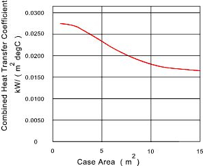
C cr = Combined (radiation/convection )heat transfer coefficient kW/( m 2. deg.C)
Δ t = Temperature difference between oil and surroundings
Ac = Area of case exposed to ambient air temperature.
A chart below provides combined heat transfer values based on gearbox exposed area..

This graph is based on information from ..Machine design Theory and Practice .A.D.Deutschman, W.A Michels & C.E. Wilson.. MacMillan Publishing 1975.
For a small gearbox with a surface temperature of 50o above ambient a heat transfer of about 1,26kW /m2 is achievable.
For a large gearbox with a surface temperature of 50o above ambient a heat transfer of about 0.8kW /m2 is achievable.
If a fan is provided on the wormshaft and improvement in C cr of about 60% is possible
Ref. watlow.com Includes
surface heat transfer information.
From this source a typical combined heat transfer coefficient for oxidised steel
for an ambient air temperature 21o. C and a body temperature of
93 o C. i.e 72o C. temperature difference is 1.0kW per m2.
Ref. Spirax Sarco
Includes a chart providing overall heat transfer values from steel tanks walls.
| Temperature surface and ambient |
U - at different relative air flows |
| Side Walls | top |
| W / (m2.oC ) | W / (m2.oC ) |
| deg.C | Static | 1m/s | 3m/s | Static | 1m/s | 3m/s |
| 30 | 10.5 | 18 | 31.5 | 14 | 24 | 42 |
| 50 | 11.5 | 20 | 34,5 | 15 | 25,5 | 45 |
| 70 | 12 | 20,4 | 36 | 16 | 27,2 | 48 |
This table includes for static air conditions and if the air flow adjacent to the
surfaces is about 1m/s then the static values are increased by a factor of 1.7 and if the air flow is
3m/s then the static values are increased by a factor of 3.
From this source a heat transfer coefficient of about 1 kW /m2 is
achievable from a tank with side walls and a top surface with a low ambient air
movement at a temperature difference of 50o C.. This would increase by about
75% if relative air flow is increased to 3m/s (equivalent to a slight breeze)
| 