Drive_Index
Gears Gearboxes
Helical Gears
|
Introduction Helical gears are similar to spur gears except that the gears teeth are at an angle with
the axis of the gears. A helical gear is termed right handed or left handed as determined
by the direction the teeth slope away from the viewer looking at the top gear surface
along the axis of the gear. ( Alternatively if a gear rests on its face the
hand is in the direction of the slope of the teeth) . Meshing helical gears
must be of opposite hand.
Meshed helical gears can be at an angle to each other (up to 90o ). The helical gear
provides a smoother mesh and can be operated at greater speeds than a straight spur gear. In operatation
helical gears generate axial shaft forces in addition to the radial shaft force generated by normal spur gears.
Helical gear parameters
A helical gear train with parallel axes is very similar to a spur gear with the same tooth
profile and proportions. The primary difference is that the teeth are machined at an
angle to the gear axis.
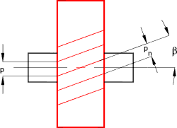
The helix angle of helical gears β is generally selected from
the range 6,8,10,12,15,20 degrees. The larger the angle the smoother the motion and the
higher speed possible however the thrust loadings on the supporting bearings also
increases.
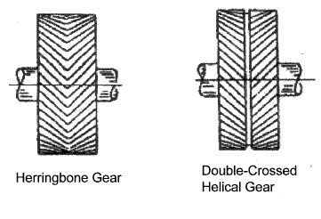
In case of a double or herringbone gear β
values 25,30,35,40 degrees can also be used. These large angles can be used because the
side thrusts on the two sets of teeth cancel each other allowing larger angles with no penalty For helical gears the circular pitch is measured in two ways
Herringbone / double crossed helical gears
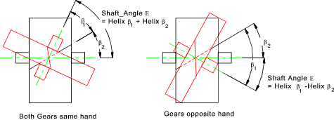
When two helical gears are used to transmit power between non parallel, non-intersecting
shafts, they are generally called crossed helical gears. These are simply normal
helical gears with non-parallel shafts. For crossed helical gears to operate successfully
they must have the same pressure angle and the same normal pitch. They need not
have the same helix angle and they do not need to be opposite hand.
The contact is not a good line contact as for parallel helical gears and is often little
more than a point contact. Running in crossed helical gears tend to marginally improve
the area of contact. E = (Same Helix Angle) β 1 + β 2 ......(Opposite Helix Angle) β 1 - β 2
The centres distance (a) between crossed helical gears is calculated as follows a = m * [(z 1 / cos β 1) + ( z 1 / cos β 1 )] / 2 The sliding velocity Vsof crossed helical gears is given by Vs = (V1 / cos β 1 ) = (V 2 / cos β 2 ) Strength and Durability calculations for Helical Gear Teeth Designing helical gears is normally done in accordance with standards the two most popular series are listed under standards above: The notes below relate to approximate methods for estimating gear strengths. The methods are really only useful for first approximations and/or selection of stock gears (ref links below). � Detailed design of spur and helical gears should best be completed using : a) Standards. The determination of the capacity of gears to transfer the required torque for the desired operating life is completed by determining the strength of the gear teeth in bending and also the durability i.e of the teeth ( resistance to wearing/bearing/scuffing loads ) .. The equations below are based on methods used by Buckingham.. Bending The Lewis formula for spur gears can be applied to helical gears with minor adjustments to provide an initial conservative estimate of gear strength in bending. This equation should only be used for first estimates. σ = Fb / ( ba. m. Y )
When a gear wheel is rotating the gear teeth come into contact with some degree of impact. To allow for this a velocity factor is introduced into the equation. This is given by the Barth equation for milled profile gears. K v = (6,1 + V ) / 6,1
σ = K v.Fb / ba. m. Y The Lewis form factor Y must be determined for the virtual number of teeth z' = z /cos3β The bending stress resulting should be less than the allowable bending stress Sb for the gear material under consideration. Some sample values are provide on this page ef Gear Strength Values Surface Strength The allowable gear force from surface durability considerations is determined approximately using the simple equation as follows Fw = K v d p b a Q K / cos2β
Q = 2. dg /( dp + dp ) = 2.zg /( zp +zp ) Fw = The allowable gear load. (MPa)
| |||||||||||||||||||||||||||||||||||||||||||||||||||||||||||||||||||||||||
Links to Gear Design
|
|
Drive_Index
Gears Gearboxes


