| |
Metal Fatigue and Endurance
Important note.. The information below is for guidance only .
Evaluating the fatigue strength to be used for component design should be carried
out using validated material information and with careful consideration of all factors relevant to the stress locations.
The links below the table provide more detailed information on fatigue design.
|
Fatigue Modifying Factors The load experience by a component subject to fatigue loading must not exceed
the MODIFIED endurance limit divided by the Stress Concentration factor (Kf).
The Modified fatigue endurance limit for, ferrous materials and titanium, is the endurance strength ( S' e ) identified from the relevant S-N ( Wohler) curve modified by a number of factors Max load (tension) < Se / K f = C s x C f x C l x C t x C r x C m x S' e / K f Max load (shear) < Ses / K f = C s x C f x C l x C t x C r x C m x S'es / K f Note: For metals which do not have a definite endurance limit e.g copper allows the endurance limts S'e, S'es etc are replaced by assumed endurance limits S'n, S'ns etc. etc...
All of the above factors have significant quantifiable negative effect on the
fatigue strength of a metal. The endurance limit of specimens have been observed to vary with their size.
This is possibly related to the probability of a high stress interacting with a critical flaw within
a certain volume, i.e., when the volume is large there is a higher probability of failure. Hence,
when the size increases, the endurance decreases. Alternatively, since there appears to be a more
pronounced size effect in reversed bending and/or torsion than in the reversed axial loading
situation this suggests that the stress gradient at the surface is partially responsible for the size
effect.
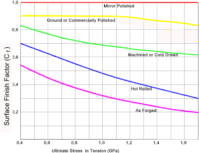
C f = Surface Finish Factor The specimens used in the laboratory to determine the fatigue strength curve or endurance limit
of a particular material have a standard size and surface finish that are closely monitored prior to
the test. As discussed previously, the initiation of microcracks is almost always associated with
a free surface and, hence, the surface condition of the location being reviewed plays a crucial
role in assessing the modified fatigue strength.
The surface finish factor can be calculated using the equation derived from this graph as follows Cf = a.Sutb Sut = tensile stresss in MPa. a and b are factors listed in table below
C l = Load factor The strength values obtained from the S-N (Wohler plot) result from a reversed bending load as the specimen is rotated. In the rotating-bending testing every element in the specimen diameter surface is subjected to a bend in one direction and then the other, with only a small region on the outer surface being subjected to the maximum stress level. The reversed axial loading scenario is a much more arduous condition because the all of the section is subject to the full stress and not just the surface elements (The strength values reported for reversed axial loading has been reported at various ratios from 0,7 - 0,85 times that reported for reversed bending ). Again in the reversed torsion scenario the loading is shear as opposed to bending. To allow for these differences a loading factor is provided.
Components are often required to endure temperatures different from those at which the mechanical properties of a material were obtained. For metals, the following relations may be applicable in certain situations. A lower temperatures and higher temperatures a more detailed assessment will be required...
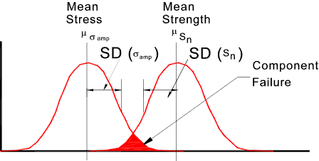
The basis of the concept of reliability is that a given component has a certain
strength resisting capacity; if the stress induced by the operating
conditions exceeds this capacity, failure results. In themselves, design
methods based solely on the use of factors of safety and margins of safety give
little indication as to the failure probability of the component under cyclic loading. Furthermore, design variables and parameters are random
variables, a fact often ignored by conventional design methods. The S_N (Wohler) plotted values are mean values based on a number of tests resulting in loads at failure.
The strength values are mean values implying a 50% survival rate. To enable determination of design strength
values with a higher survival rate i.e upwards then the indicated strength values must be reduced..This involves
the use of the Reliability factor determined by statistical adjustment of the 50% value S'n.....Put simply
, "increasing the factor of safety results in lower risk of failure "
This factor is a general factor to allow for various factors which are not easily quantifiable.
These factors may include the influence of: corrosion, electrolytic plating (metallic coatings),
metal spraying, cyclic frequency, fretting corrosion (due to microscopic
motions of tightly fitted parts), and radiation effects on materials. When corrosion, for example, is
combined with cyclic loading, failure is likely to be more accelerated and the endurance limit
lower than expected from separate estimates of the two factors. The reason for this is that
corrosion and stressing occur not only at the same time but also interact with one another. As
another example, in regions where bearing loads exist, the risk of fretting corrosion occurring is
higher than at other locations of a component. As a result, the value of Cm should
be lower in these locations than at others. Hence, in a particular situation
actual fatigue data may not be applicable and an estimate of Cm must be included in the
design and material selection process.
|
Fatigue Links
|
|
Please Send Comments to Roy Beardmore