Fatigue Life
Cyclic Loading Life Considerations
A component is stressed to some extent in its operating life.
In all loading scenarios it is desirable to design the component to minimise stress concentrations
and maximum the strength of the component material using good design practices.
1) Static Loading..
If the component is stressed to a constant stress level for its operating life then fatigue loading
design is not appropriate and for ductile materials the stress concentration factors are
not important...If the component is brittle e.g. Cast Iron, then the stress concentration factors
need to be considered in the design process..Design using the material yield strength and
ultimate strength using the appropriate strength formulae and Factors of Safety can be completed
2) Low life Loading -Stress cycles < 10 3 stress cycles over the design life.
This condition is approached in a similar manner to the static loading scenario.
There is a need to review the loading with respect to the material fatigue properties
Approximate values for low life fatigue strength values for steel are provided below
- Bending S'l = 0,9 Su
- Axial Loading S'l = 0,75 Su
- Axial Loading S'l = 0,72 Su
|
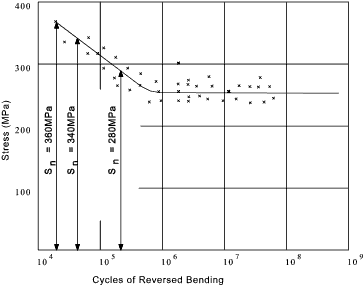
3) Finite life Loading - Stress cycles 10 3 to 10 6 stress cycles over design lifetime
Use S-N (Wohler) curve for relevant material and determine the relevant fatigue stress level at the
relevant design life . If this information is not available then
an estimate of the fatigue strength S'f can be made if the Endurance limit and the
Low life strength values are available. ref. High life fatigue strength
The fatigue modifying factors must be considered
and the stress concentration factors should also be considered. If the cyclic stress
level at at different values over the operating lifetime then it may be appropriate to use
the Palmgren-Miner rule see below..
3) Infinite life Loading - Stress cycles >10 6 stress cycles design lifetime
For ferrous metals and titanium alloys the endurance limit may be used S'n.
For non ferrous the fatigue strength limit S'n may be used,with care ,
as a design material strength (assuming the n-cycles.
used is similar compared to the projected life).
The S'n value to be modified by the appropriate fatigue modifying factors and the design should apply
appropriate stress concentration values and factors of safety..
Palmgren-Miner
In actual service, parts are seldom stressed repeatedly at only one stress level
and, hence, the problem arises as to the cumulative damage effect of operations
at various levels of stress reversal.
Consequently, the linear cumulative damage rule or the Palmgren-Miner rule has
come into common usage. It assumes that the total life of a part
may be estimated by merely adding up the percentage of life consumed by each
stress cycle.
Thus, if a specimen, stressed at s1,
has a life of N 1 cycles, the damage after
n 1 cycles at s1
will be n 1 / N 1 of the total damage,
D, at failure. Similarly, for a two stress level test,
where the lives at s1 and
s2 are,
respectively, N 1 and N 2, the corresponding
damages, per cycle, being D/N 1 and D/N 2 the total damage
at failure becomes:D = D . n 1 / N 1 + D . n 2 / N 2
or 1 = n 1 /N 1 + n 2 / N 2
where n 1 and n 2 are the total number of cycles at s1 and s1,
respectively.
For a multi-level test,
Palmgren - Miner rule states
Failure if n 1 / N 1 + n 2 / N 2 + n3 / N3...... > 1
Example :
A component is designed for
- a stress of 360MPa for 8,000 cycles. Life N 1 from S_N curve = 20,000 cycles
- a stress of 340MPa for 10,000 cycles. Life N 2 from S_N curve = 40,000 cycles
- a stress of 280MPa for 40,000 cycles. Life N 3 from S_N curve = 200,000 cycles
|

8,000 / 20,000 + 10,000/40,000 + 40,000 / 200,000 = 0.8 ( This is less than 1) ..The part will probably not fail in fatigue..
|
