Stress Concentration Factors Notes
The theoretical stress concentration factor K t of a section at subject to an internal stress resulting
from a change of shape and/or geometry :
K t = Highest value of stress at a discontinuity / Nominal stress at local minimum section
K ts relates to shear stress.
This value does not allow for the sensitivity of the material to stress concentrations.
Notch Sensitivity
The material notch sensitivity value "q" is
used to quantify the sensitivity of a material
to local high stresses. The notch sensitivity of a material is a measure
of how sensitive a material is to notches or
geometric discontinuities.
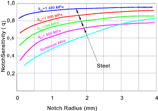
High notch sensitivity..
Brittle/Hard Materials
Very perfect material is significantly damaged by addition of a notch
Low Notch sensitivity
Material with a lot of flaws not damaged much by one more.
Soft Ductile Materials..
In fatigue assessments K f is used in place of K t
K f = 1 + q (K t -1). :: ..1 <= k f <= k t
If values for q are not available it is conservative (safe) to use K t.
Stress Concentration Factors
Note: These values have been obtained by reference to..
- Machinery's Handbook 18th ed.
- Mechanical Engineers Data Book (J.Carvill)
- Machine Design-Theory & Practice A.D Deutschman, W.J Michels, C.E. Wilson
- The calculators in the links below (ETB and Stacie Glass)
|
All of the sources provided similar results (+/- 10%)..Some source results are tabulated and
some are graphs. My tables include for a degree of mix and match and should be used as such..
(The best source of Stress Concentration Factors (and probably the source for the above references)
is Peterson's Stress Concentration Factors (2nd Edition)...by Pilkey, Walter D. � 1997 John Wiley & Sons ...)
If serious work is being carried out reputable sources of information should be used..
Plate with hole in centre of width
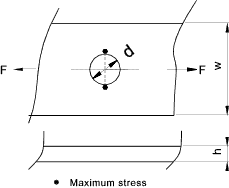
K f = smax / s
| d / w |
0,00 |
0,10 |
0,20 |
0,30 |
0,40 |
0,50 |
0,55 |
| K t |
3,00 |
3,03 |
3,14 |
3,34 |
3,69 |
4,25 |
4,64 |
Wide plate with hole near one side
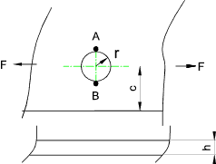
- sa= Stress at A
- sb= Stress at B
- s= Calculated uniform stress in section including hole
|
K t_a = sa / s :: K t_b = sb / s
| r / c |
0,00 |
0,10 |
0,20 |
0,30 |
0,40 |
0,50 |
0,60 |
0,70 |
0,80 |
0,85 |
| K t_a |
3,00 |
3,01 |
3,05 |
3,20 |
3,44 |
3,78 |
4,24 |
4,84 |
5,63 |
6,11 |
| K t_b |
3,00 |
3,03 |
3,07 |
3,10 |
3,15 |
3,18 |
3,25 |
3,32 |
3,42 |
3,50 |
Tension of Stepped bar with filleted corners
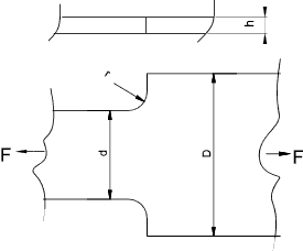
K t = smax / ( F /h.d)
| D/d | r/d |
| 0,01 |
0,02 |
0,04 |
0,06 |
0,10 |
0,15 |
0,20 |
0,25 |
0,30 |
| 1,01 |
1,65 |
1,46 |
1,32 |
1,26 |
1,20 |
1,18 |
1,15 |
1,13 |
1,12 |
| 1,02 |
1,91 |
1,64 |
1,46 |
1,37 |
1,33 |
1,31 |
1,26 |
1,25 |
1,20 |
| 1,05 |
2,43 |
2,02 |
1,72 |
1,59 |
1,45 |
1,40 |
1,35 |
1,30 |
1,28 |
| 1,10 |
3,02 |
2,43 |
1,98 |
1,78 |
1,63 |
1,51 |
1,44 |
1,39 |
1,36 |
| 1,20 |
3,74 |
2,98 |
2,38 |
2,14 |
1,89 |
1,72 |
1,62 |
1,56 |
1,53 |
| 1,30 |
4,27 |
3,40 |
2,67 |
2,38 |
2,06 |
1,86 |
1,73 |
1,64 |
1,59 |
| 1,50 |
4,80 |
3,75 |
3,00 |
2,64 |
2,24 |
1,99 |
1,84 |
1,74 |
1,67 |
| 2,00 |
|
|
3,74 |
3,2 |
2,65 |
2,31 |
2,1 |
1,94 |
1,85 |
Bending of Stepped bar with filleted corners
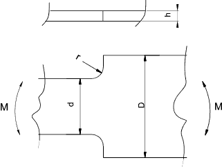
K t = smax / ( 6.M /h.d2)
| D/d | r/d |
| 0,01 |
0,02 |
0,04 |
0,06 |
0,10 |
0,15 |
0,20 |
0,30 |
| 1,01 |
1,76 |
1,53 |
1,37 |
1,32 |
1,28 |
1,25 |
1,22 |
1,19 |
| 1,02 |
2,05 |
1,74 |
1,52 |
1,42 |
1,35 |
1,28 |
1,25 |
1,22 |
| 1,05 |
2,58 |
2,11 |
1,77 |
1,62 |
1,47 |
1,40 |
1,34 |
1,29 |
| 1,10 |
3,09 |
2,45 |
2,00 |
1,80 |
1,59 |
1,49 |
1,40 |
1,31 |
| 1,20 |
3,62 |
2,81 |
2,23 |
1,97 |
1,70 |
1,55 |
1,44 |
1,34 |
| 1,50 |
3,80 |
2,98 |
2,38 |
2,15 |
1,83 |
1,63 |
1,52 |
1,38 |
| 2,00 |
|
3,14 |
2,59 |
2,23 |
1,88 |
1,66 |
1,54 |
1,40 |
| 3,00 |
|
3,30 |
2,68 |
2,34 |
1,93 |
1,67 |
1,53 |
1,38 |
Torsion of Grooved Shaft
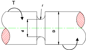
K ts = tmax / ( 16.T /p.d3)
| D/d | r/d |
| 0,02 |
0,03 |
0,04 |
0,06 |
0,10 |
0,15 |
0,20 |
0,30 |
| 1,05 |
2,00 |
1,80 |
1,60 |
1,45 |
1,34 |
1,28 |
1,21 |
1,15 |
| 1,10 |
2,00 |
1,84 |
1,74 |
1,63 |
1,45 |
1,35 |
1,29 |
1,22 |
| 1,20 |
2,16 |
1,97 |
1,85 |
1,69 |
1,51 |
1,39 |
1,32 |
1,24 |
| 1,30 |
2,22 |
2,02 |
1,89 |
1,72 |
1,59 |
1,39 |
1,33 |
1,24 |
| 1,50 |
2,24 |
2,03 |
1,90 |
1,73 |
1,53 |
1,39 |
1,30 |
1,25 |
| 2,00 |
2,80 |
2,10 |
1,93 |
1,75 |
1,55 |
1,41 |
1,31 |
1,20 |
Bending of Grooved Shaft
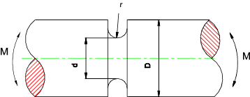
K t = smax / ( 32.M /p.d3)
| D/d |
r/d |
| 0,04 |
0,06 |
0,10 |
0,15 |
0,20 |
0,25 |
0,30 |
| 1,05 |
2,33 |
2,04 |
1,76 |
1,60 |
1,50 |
1,42 |
1,36 |
| 1,10 |
2,45 |
2,14 |
1,85 |
1,64 |
1,53 |
1,45 |
1,39 |
| 1,20 |
2,63 |
2,30 |
1,92 |
1,70 |
1,57 |
1,48 |
1,42 |
| 1,30 |
2,71 |
2,35 |
1,95 |
1,72 |
1,58 |
1,49 |
1,43 |
| 1,50 |
2,85 |
2,40 |
2,00 |
1,74 |
1,60 |
1,51 |
1,43 |
| 2,00 |
2,95 |
2,45 |
2,10 |
1,83 |
1,67 |
1,55 |
1,45 |
Torsion of Stepped Shaft
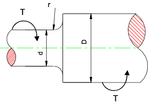
K ts = tmax / ( 16.T /p.d3)
| D/d | r/d |
| 0,02 |
0,03 |
0,05 |
0,07 |
0,10 |
0,15 |
0,20 |
0,30 |
| 1,05 |
1,56 |
1,45 |
1,34 |
1,27 |
1,22 |
1,17 |
1,14 |
1,10 |
| 1,10 |
1,72 |
1,57 |
1,43 |
1,35 |
1,28 |
1,21 |
1,17 |
1,12 |
| 1,20 |
2,0 |
1,70 |
1,57 |
1,42 |
1,33 |
1,25 |
1,20 |
1,15 |
| 1,30 |
2,03 |
1,79 |
1,56 |
1,44 |
1,35 |
1,26 |
1,21 |
1,15 |
| 1,50 |
2,20 |
1,92 |
1,62 |
1,47 |
1,36 |
1,25 |
1,20 |
1,14 |
| 1,75 |
2,30 |
2,05 |
1,75 |
1,60 |
1,45 |
1,30 |
1,24 |
1,16 |
| 2,00 |
2,55 |
2,15 |
1,75 |
1,6 |
1,45 |
1,31 |
1,24 |
1,16 |
| 2,50 |
2,60 |
2,30 |
1,80; |
1,65 |
1,42 |
1,31 |
1,25 |
1,16 |
Bending of Stepped Shaft
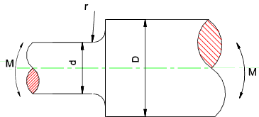
K t = smax / ( 32.M /p.d3)
| D/d | r/d |
| 0,01 |
0,02 |
0,03 |
0,04 |
0,05 |
0,08 |
0,10 |
0,15 |
0,20 |
0,25 |
| 1,01 |
2,05 |
1,90 |
1,70 |
1,60 |
1,55 |
1,41 |
1,36 |
1,26 |
1,20 |
1,15 |
| 1,02 |
1,96 |
1,64 |
1,54 |
1,46 |
1,41 |
1,34 |
1,32 |
|
|
|
| 1,05 |
2,50 |
2,25 |
2,00 |
1,85 |
1,78 |
1,60 |
1,54 |
1,41 |
1,32 |
1,25 |
| 1,10 |
2,80 |
2,34 |
2,08 |
1,94 |
1,85 |
1,65 |
1,54 |
1,43 |
|
|
| 1,20 |
3,30 |
2,60 |
2,30 |
2,10 |
1,95 |
1,75 |
1,65 |
1,50 |
1,42 |
1,30 |
| 1,50 |
3,73 |
2,90 |
2,52 |
2,30 |
2,13 |
1,84 |
1,72 |
1,54 |
1,43 |
1,35 |
| 2,00 |
3,70 |
3,17 |
2,71 |
2,42 |
2,25 |
1,92 |
1,78 |
1,58 |
1,46 |
1,36 |
| 3,00 |
3,90 |
3,30 |
2,90 |
2,45 |
2,35 |
1,96 |
1,81 |
1,61 |
1,48 |
1,38 |
Stress concentration factor for keyways
Note: Values below are K f not K t
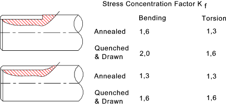
Keyways cut into a shaft reduce its normal torque carrying capacity..It is accepted that for a standard
keyway (width approx 25% dia and depth approx 12.5% dia) the design load carrying capacity is reduced to
75% of the normal working strength.. (before application of any stress concentration factors>.
Stress Concentration Factor for Screw Threads
Note: Values below are K f not K t
| Bending or Tension K f |
| | Rolled | Cut |
| Annealed | 2,2 | 2,3 |
| Quenched & Drawn | 3,0 | 3,8 |
Stress Concentration Factor for Welds
Note: Values below are K f not K t..Some text books allow for welds
using a fatigue strength modifying factor and not a stress concentration modifying factor
| Weld Type | K f | Picture |
| Reinforced Butt Weld | 1,2 |  |
| Traverse Fillet Weld | 1,5 | < |
| Parallel Fillet Weld | 2,7 |  |
| Tee butt with Fillet Weld (No Penteration) | 2,0 |  |
|


