|
Introduction
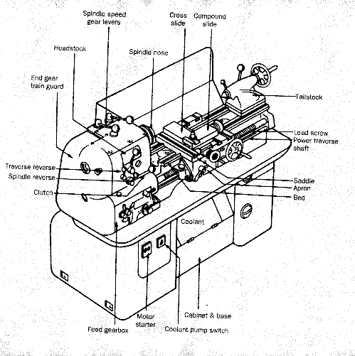
The lathe is available in many forms as listed below. All lathes are based upon the
centre lathe as shown in the figure below;
The basic operations that can be carried out on lathes include:-Turning,
Facing, Boring, Drilling, Reaming, Counterboring, Countersinking, Threading,
Knurling and Parting.
Types of Lathes
- Centre lathes
Engine lathes,
Bench lathes,
Toolroom lathes,
Speed lathes,
Duplicating lathes,
Production lathes,
Vertical lathes,
- Capstan/Turret lathes
- Automatic lathes
|
Center Lathes

All of the important features of the lathe are shown on the above figure.
The headstock spindle which is hollow to allow bar stock to be fed through is generally provided
with a special male thread to allow chucks etc. to be easily fitted and removed. Some of the different work holding
units which can be fitted onto the headstock spindle are shown below.

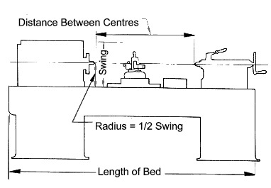
Important Centre Lathe Dimensions
Work Holding Devices

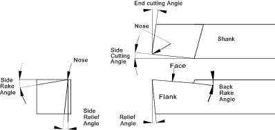
Cutting Tool Terms
- Face ..top surface of cutting tool
- Cutting Edge ..The part of the cutting tool which actually cuts the metal comprises the side cutting edge and the end cutting edge
- Flank ..The side of the cutting tool below the side cutting edge
- Nose ..Point to the tool
- Nose Radius ..The radius of the nose - 0,4mm for heavy cuts ,0,4-1,5mm for finishing cuts
- Nose Angle ..Plan angle between the side cutting edge and the end cutting edge
- Side Cutting Edge angle ..Angle between the side cutting edge and the line of the shank side
- End cutting edge angle ..Angle between the end cutting edge and a line drawn 90o to the shank side
- Side Relief/clearance Angle ..The angle between the tool flank and the original side of the tool
- End Relief/clearance Angle ..The angle between the end of tool and a line drawn 90o to the Centre line of the Lathe
- Side Rake ..Angle between the tool face and the horizontal Plane parallel to the axis of the lathe
- Back Rake Rake ..Angle between the tool face and the horizontal Plane 90o to the axis of the lathe
|

Cutting Speeds
The cutting speed is the speed at which the work surface passes the cutting tool.
This is mainly dependent on the material being turned and the cutting tool material.
The table below indicates some approximate cutting speed for turning on a lathe.
For information on cutting materials refer Cutting Materials. For information
on cutting fluids refer Cutting Fluids
| Material |
Cutting Tool
Material |
Rough
Cut |
Finishing
Cut |
| m/min |
m/min |
| Free Cutting Steel |
H.S.S |
35 |
90 |
| Cast Alloy |
75 |
145 |
| Carbide |
125 |
205 |
| Low Carbon Steel |
H.S.S |
31 |
80 |
| Cast Alloy |
65 |
130 |
| Carbide |
106 |
190 |
| Medium Carbon Steel; |
H.S.S |
30 |
69 |
| Cast Alloy |
58 |
107 |
| Carbide; |
92 |
152 |
| High Carbon Steel |
H.S.S |
24 |
61 |
| Cast Alloy |
53 |
91 |
| Carbide |
76 |
137 |
| Cast Iron Grey |
H.S.S |
24 |
41 |
| Cast alloy |
43 |
76 |
| Carbide |
69 |
125 |
Brass / Bronze
Free Cutting |
H.S.S |
53 |
110 |
| Cast Alloy |
105 |
170 |
| Carbide |
175 |
275 |
| Aluminium |
H.S.S |
40 |
90 |
| Cast Alloy |
55 |
115 |
| Carbide |
75 |
185 |
| Plastics |
H.S.S |
30 |
75 |
| Cast Alloy |
45 |
115 |
| Carbide |
60 |
150 |
|


