Introduction
Rivets are considered to be permanent fasteners. Riveted joints
are therefore similar to welded and adhesive joints. When considering
the strength of riveted joints similar calculations are used as for bolted joints.
Rivets have been used in many large scale applications including shipbuilding,
boilers, pressure vessels, bridges and buildings etc. In recent years
there has been a progressive move from riveted joints to welded, bonded and even
bolted joints A riveted joint, in larger quantities is sometimes cheaper than the other options but it requires
higher skill levels and more access to both sides of the joint
There are strict standards and codes for riveted joints used for structural/pressure vessels
engineering but the standards are less rigorous for using riveted joints in general
mechanical engineering.
A rivet is a cylindrical body called a shank with a head. A hot rivet is inserted into a hole passing
through two clamped plates to be attached and the head is supported whilst a head is
formed on the other end of the shank using a hammer or a special shaped tool. The plates are
thus permanently attached. Cold rivets can be used for smaller sizes the - forming processes being
dependent on the ductility of the rivet material...

When a hot rivet cools it contracts imposing a compressive (clamping) stress on the
plates. The rivet itself is then in tension the tensile stress is approximately equal to
the yield stress of the rivet material
Strength of riveted joint
The notes below are assuming that the plate loads are withstood by the rivets. In practice
the loads are generally withstood by friction between the plates under the compressive force
of the contracted rivets. The calculations provided below are simplified
but provide relatively conservative joint strength value. There is still a need to
complete fatigue assessments on joints when relevant
Joint Types
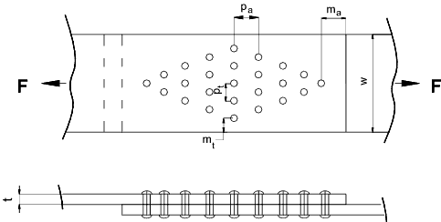
There are two basic types of axial riveted joint the lap joint and the butt joint.

The selection of the number of rivets used for a joint and the array is simply to ensure
the maximum strength of the rivets and the plates. If ten small arrayed rivets on a lap
joint were replaced by three large rivets across a plate the plate section area (in tension) would clearly
be significantly reduced...
Rivet materials
Rivets for mechanical and structural applications are normally made from ductile (low carbon ) steel
or wrought iron. For applications where weight, corrosion, or material
constraints apply, rivets can be made from copper (+alloys) aluminium (+alloys),monel etc.
Design stresses
For rivets used for structures and vessels etc the relevant design stresses are provided
in the applicable codes. For rivets used in mechanical engineering, values are available
in mechanical equipment standards which can be used with judgement.
BS 2573 Pt 1 Rules for the design of cranes includes design stress values based on the
Yields stress (0,2% proof stress) YR0.2 as follows:-
Hand driven rivets ..tensile stress (40%YR0.2) ..Shear (36,6%YR0.2)..Bearing (80%YR0.2)
Machinery's handbook includes some values for steel rivets . I have intepreted these values and include
them below as rough approximate values for first estimate. These are typical values
for ductile steel. Tensile (76MPa) .. Shear (61MPa) ..Bearing (131MPa)
Design Assumptions
In designing rivet joints it is convenient to simplify the process by making
the following assumptions.
- The rivets fail in either pure compression, or pure shear.
- The shear stress is evenly distributed across the rivet section.
- The bearing stress is evenly distributed across the projected area of the rivet.
- The force to cause a rivet to fail in double shear is 2 x the force to cause single shear failure.
- the tensile stress is uniform across the plate area between the rivets.
|
Rivet Joint Failure
A rivet joint may fail as a result of one( or more) of a number mechanisms..
- Shearing through one section of the rivet (single shear).
- Shearing through two sections of the rivet (double shear.
- Compressive bearing failure of the rivet.
- Shearing of the plate(s) being joined.
- Bearing failure of the plate(s) being joined.
- Tearing of the plates between the rivets.
|
Rivet Joint Efficiency
The rivet joint effieciency is simply described as follows
Eff = Max Allowable Force applied to Rivet Joint/ Plate Strength with not holes
The joint efficiency is increased by having multiple rows of rivets. It is also clear
that the efficiency can never be 100% . The maximum allowable force is the smallest of the
allowable shear, tensile or bearing forces.

Rivets are initially sized with nominal diameters of between 1,2√ t and 1,4 √t (t = plate thickness)
The diametrical clearance provided for hot rivets is about 1,5mm max. For cold
rivets very tight fits are often provided by using reamed holes. It is important
that the rivets are not positioned too close to the side of the plate or the edge of a
plate. m t should be greater than 1,5 d and m a should be
greater than 1,5 d. (d = nominal rivet diameter). It is also suggested that
the distance between rivets in the rows (pt) is greater than 3d and the
distance between rows (pa )is greater than 3 d. Uisng these
guidance factors the strength calculations are simplified
Rivets calculations are generally completed to check for three failure modes : rivet shear,
plate tensile failure, and rivet /plate bearing..These are shown below. A
rivet joint can also fail due to plate shearing (tearing )behind the rivet.
This calculation is not always completed because the joint design should include that the minimim metal land behind the
rivet (ma above )is specified ensuring that other failure modes will operate before this mode.
It is also important that the axial pitch (p a ) is maximised (see above note )to
ensure that the weakest section of the plate is through a row of holes

Rivet Shear
The rivet shear calculation is
τ = F / ( n p d 2 /4 )
- τ = Shear Stress (MPa)
- d = rivet diameter (mm)
- F = Total Axial Force (N)
- n = Number of Rivets
|
Plate Tensile Stress
The tensile stress in the plate =
σt = F / [t (w - n r d 1)
- σt = Tensile Stress (MPa)
- d 1= rivet hole diameter (mm)
- n r = Number of Rivets in a row across the plate
|
Plate /rivet bearing stress
The Plate/Rivet bearing stress =
σc = F /(n d t)
Plate tearing stress..
The plate shear stress =
τc = F /(2 m a t)
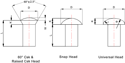
Hot Forged Rivets to BS 4620: 1998
Note: The Standard BS 4620 has been declared obsolescent as it is no longer used for
current technologies....

Nom
Shank
dia |
Dia
Tol |
60 Deg Csk & Raised Csk |
Snap Hd |
Universal Hd |
| Nom dia |
Raise Ht |
Nom dia |
Nom Depth |
Nom dia |
Nom Depth |
Rad |
Rad |
| D |
W |
D |
K |
D |
K |
R |
r |
| 14 |
+/- 0,43 |
21 |
2,8 |
22 |
9 |
28 |
5,6 |
42 |
8,4 |
| 16 |
+/- 0,43 |
24 |
3,2 |
25 |
10 |
32 |
6,4 |
48 |
9,6 |
| 18 |
+/- 0,43 |
27 |
3,6 |
28 |
11,5 |
36 |
7,2 |
54 |
11,0 |
| 20 |
+/- 0,52 |
30 |
4,0 |
32 |
13 |
40 |
8,0 |
60 |
12,0 |
| 24 |
+/- 0,52 |
33 |
4,4 |
36 |
14 |
44 |
8,8 |
66 |
13,0 |
| 24 |
+/- 0,52 |
36 |
4,8 |
40 |
16 |
48 |
9,6 |
72 |
14,0 |
| 27 |
+/- 0,62 |
40 |
5,4 |
43 |
17 |
54 |
10,8 |
81 |
16,0 |
| 30 |
+/- 0,62 |
45 |
6,0 |
48 |
19 |
60 |
12,0 |
90 |
18,0 |
| 33 |
+/- 0,62 |
50 |
6,6 |
53 |
21 |
66 |
13,2 |
99 |
20 |
| 36 |
+/- 0,62 |
55 |
7,2 |
58 |
23 |
72 |
14,4 |
108 |
22 |
| 39 |
+/- 0,62 |
59 |
7,8 |
62 |
25 |
78 |
15,6 |
117 |
23 |
Cold Forged Rivets to BS 4620: 1998
Note: The Standard BS 4620 has been declared obsolescent as it is no longer used for
current technologies....

| Nominal Shank dia |
Dia
Tol |
90 Deg Csk |
Snap Hd |
Universal Hd |
Flat Head |
| Nom dia |
Nom dia |
Nom Depth |
Nom dia |
Nom Depth |
Rad |
Rad |
Nom dia |
Nom Depth |
| D |
D |
K |
D |
K |
R |
r |
D |
K |
| 1 |
+/- 0,07 |
2 |
1,8 |
0,6 |
2 |
0,4 |
3,0 |
0,6 |
2 |
0,25 |
| 1,2 |
+/- 0,07 |
2,4 |
2,1 |
0,7 |
2,4 |
0,5 |
3,6 |
0,7 |
2,4 |
0,3 |
| 1,6 |
+/- 0,07 |
3,2 |
2,8 |
1,0 |
3,2 |
0,6 |
4,8 |
1,0 |
3,2 |
0,4 |
| 2,0 |
+/- 0,07 |
4 |
3,5 |
1,2 |
4 |
0,8 |
6,0 |
1,2 |
4 |
0,6 |
| 2,5 |
+/- 0,07 |
5 |
4,4 |
1,5 |
5 |
1 |
7,5 |
1,5 |
5 |
0,8 |
| 3 |
+/- 0,07 |
6 |
5,3 |
1,8 |
6 |
1,2 |
9,0 |
1,8 |
6 |
0,9 |
| 3,5 |
+/- 0,09 |
7 |
6,1 |
2,1 |
7 |
1,4 |
10,5 |
2,1 |
7 |
1,0 |
| 4 |
+/- 0,09 |
8 |
7 |
2,4 |
8 |
1,6 |
12 |
2,4 |
8 |
1,3 |
| 5 |
+/- 0,09 |
10 |
8,8 |
3,0 |
10 |
2,0 |
15 |
3,0 |
9 |
1,5 |
| 6 |
+/- 0,09 |
12 |
10,5 |
3,6 |
12 |
2,4 |
18 |
3,6 |
10 |
1,8 |
| 7 |
+/- 0,11 |
14 |
12.3 |
4,2 |
14 |
2,8 |
21 |
4,2 |
14 |
2,0 |
| 8 |
+/- 0,11 |
16 |
14 |
4,8 |
16 |
3,2 |
24 |
4,8 |
16 |
2,5 |
| 10 |
+/- 0,11 |
20 |
18 |
6,0 |
20 |
4,0 |
30 |
6,0 |
20 |
|
| 12 |
+/- 0,14 |
24 |
21 |
7,2 |
24 |
4,8 |
36 |
7,2 |
|
|
| 14 |
+/- 0,14 |
|
25 |
8,4 |
28 |
5,6 |
42 |
8,4 |
|
|
| 16 |
+/- 0,14 |
|
28 |
9,6 |
32 |
6,4 |
48 |
9,6 |
|
|
Blind Rivets (pop rivets )
Solid rivets require access to both sides of a joint and require some skill for correct
installation. Blind rivets have been developed to solve both of these
shortcomings.
Blind rivets are available in a range of body styles such as open , closed end ,multi-grip, and peel
with head styles in dome, countersunk and large flange and in materials such as
aluminium, steel, nickel copper, copper, plastic and stainless steel.
Blind rivets are normally supplied in sizes up to 8mm and able to clamp two plates with
total thickness up to 25mm (normal) 50mm (special). For steel rivets which
are not as ductile as copper /aluminium rivets the size limit is restricted to about 6mm.
Standard Pop Rivet
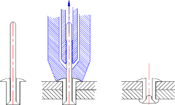
This is used for all open blind riveting locations for normal materials with
no structural or access problems. The rivet is a hollow tube of relatively soft
material with a formed head on one side. The rivet is pre-assembled on a headed mandrel
made from a stronger material than the rivet, the plain end of the madrel projecting
a relatively high distance through the head of the hollow rivet. The rivet
shank is inserted through the hole in the parts to be joined such that it projects a
set distance out of the far end of the hole. The mandrel is pulled through
the rivet using a special tool causing the projecting end to be upset. The mandrel
is engineered to snap at a set tension resulting in the correct formed head on the far side
and the joint being under compression...

Sealed Pop Rivet
This rivet is used where the joint has to be fluid pressure tight. The end include a sealed
end completely enclosing the head end of the mandrel and 100% mandrel head retention.
This feature combined with the fact that the rivet expands radially to fill the hole when set ensures that
the rivet will seal at pressures up to 35 bar

Peel type Pop Rivet
This type of rivet is used in soft materials including wood, plastic, glass fibre etc. It is
often used to fasten sheets of soft material to metals sheets. The peel type rivet
has a soft metal body e.g. aluminum with a stronger steel metal. On setting the the far
end of the rivet body splits into a number of petals creating a large blind side gripping area capable of
withstanding large pull out forces.

Grooved body type Pop Rivet
This type of pop rivet has been designed for use with thick sections of soft , or brittle material
e.g. hardboard, plywood,, glassfibre, asbestos board, brick, concrete etc.
These rivets include a shank with a number of grooves which protrude into the material to be
fixed. On setting these grooves are expanded to grip the material as opposed of the
rear face.

Strength of blind rivets (compared to solid rivets )
The strength of blind rivets as given in suppliers tables is generally the ultimate
strength at failure. In comparing the strength of blind rivets with
conventional solid rivets (same material ) the solid rivets are generally stronger than blind rivets
for the blind rivets where the blind rivet mandrel breaks off below the shear line.
For the blind rivets where the mandrel breaks off above the shear line the blind rivets
are generally stronger.
As an example for a 4mm blind rivet the shear strength quoted is 3,1kN (mandrel not
in shear plane) and 6,7kN (mandrel in shear plane. The ultimate shear
strength of a solid rivet of 4mm dia (assuming a shear strength of about 336 MPa) = 4.2 kN.
It must be noted that a blind rivet is normally used for lighter structures with thinner
section plates. It is generally accepted that a solid rivet correctly
installed is more reliable compared to a blind rivet but considerably more expensive
to fit.
|


