Introduction
The notes below show the principles used in calculating the
strength of axially loaded timber members. The principles used relate to columns , stanchions, and struts. For members loaded in compression the primary failure mode is buckling. It is important to note that
the notes below are outline notes. For detailed calculations it is necessary to refer to the identified codes.
The principles used are based on the requirements
of BS 5268;Part 2.
Axially loaded members are often also subject to other loads i.e. bending and torsional loads. The notes below
only relate to members subject to concentric axial loads.
Symbols / Units
a = distance (m)
α = angle of grain (deg /rads)
A = Area (m2)
b = breadth of beam/thickness (m)
E = Modulus of Elasticity (N/m2
Emean = mean value Modulus of Elasticity (N/m2
Emin = min value Modulus of Elasticity (N/m2
G = Modulus of Rigity (N/m2 /Pa
h = depth of section (m)
i =radius of gyration (m)
I = Second Moment of Area (m4
L =Length /span/ (m)
Le =Effective Length /Effective span (m)
m = mass (kg)
n = number
λ = slenderness ratio
Q = First moment of area(m3
ρaverage = average density (kg / m3)
M = Moment (Nm)
σm.a,ll = Applied bending stress parallel to grain (N/m2)
σm.g,ll = Grade bending stress parallel to grain (N/m2)
σm.adm,ll = Permissible bending stress parallel to grain (N/m2)
|
Fv = Applied shear Force (N)
τm.a,ll = Applied shear stress parallel to grain (N/m2)
τm.g,ll = Grade shear stress parallel to grain (N/m2)
τm.adm,ll = Permissible shear stress parallel to grain (N/m2)
τr.a,ll = Applied rolling shear stress parallel to grain (N/m2)
τr.adm,ll = Permissible rolling shear stress parallel to grain (N/m2)
Δm = bending deflection (m)
Δs = shear deflection (m)
Δtotal = total deflection (shear + bending) (m)
Δadm = pemissible deflection (m)
σc.a,ll = Applied compressive stress parallel to grain (N/m2)
σc.g,ll = Grade compressive stress parallel to grain (N/m2)
σc.adm,ll = Permissible compressive stress parallel to grain (N/m2)
σc.a,l- = Applied compressive stress normal to grain (N/m2)
σc.g,l- = Grade compressive stress normal to grain (N/m2)
σc.adm,l- = Permissible compressive normal parallel to grain (N/m2)
σt.a,ll = Applied tensile stress parallel to grain (N/m2)
σt.g,ll = Grade tensile stress parallel to grain (N/m2)
σt.adm,ll = Permissible tensil stress parallel to grain (N/m2)
|
Relevant Standards..For comprehensive list of standards Wood related Standards
BS 5268 -2 ;2002 Structural use of timber � Part 2: Code of practice for permissible
stress design, materials and workmanship.
Design Methods
In respect to columns subject to compression it is importatant the note that limit for out of
straightness is L/300 for timber sections and L/500 for glued (Glulam) sections.
Failure due to buckling is caused by the following.
- Inherent eccentricity of loading to centroid of section
- Imperfections in timber cross section.
- Non-uniformity of timber material.
|
The effect of these variables is to introduce initial bending with consequent bending stresses
which result in failure much earlier than would result from compressive stresses alone.
Failure due to buckling is related to
- The cross section of the column
- The slenderness.
- The permissible stress of the material.
|
The slenderness is calculated using the equation

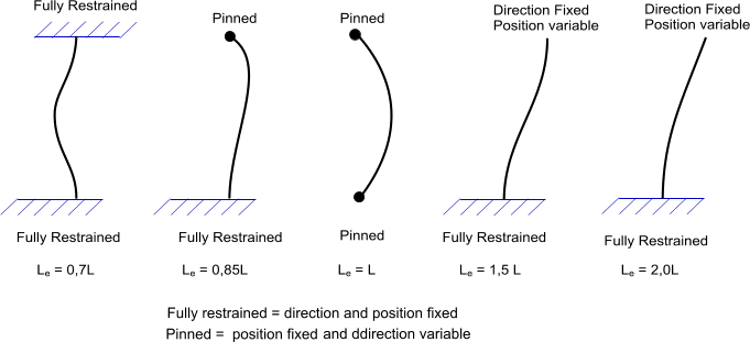
The effective length Le is related to the actual length L depending on the end conditions as shown in the figure below.

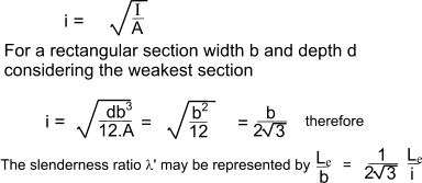
The radius of gyration is calculated as follows..

The maximum slenderness ratio is, according to the BS EN 5268-2, as follows.
- The slenderness ratio has a maximum value of 180
- any compression member carrying dead and imposed loads other than loads resulting from winds
- any compression member , however loaded , which by its deformation will adversely affect the stress in another member carrying dead and imposed loads other than wind.
The slenderness ratio has a maximum value of 250
- any member normally subject to tension or combined tension and bending arising from dead and imposed loads bu subject to a reversal of strees only from wind
- any compression member, carrying only self weight nad wind loads..
|
For compression members with slenderness ratios of less than 5, without undue eccentricity of loading, the
permissible stress should be taken as the grade compression parallel to the grain stress modified as
appropriate for moisture content, duration of loading and load sharing.
σc,adm,ll = σc,g,ll.K2.K3.K8
For compression members with slenderness ratios equal to or greater than 5, the permissible stress should
be calculated as the product of the grade compression parallel to the grain stress, modified as appropriate
for moisture content, duration of loading and load sharing, and the modification factor, K12 as provided in table below
σc,adm,ll = σc,g,ll.K2.K3.K8.K12
| E /σc,ll | Value of K12 |
| Values of slenderness ratio =λ |
| < 5 |
5 |
10 |
20 |
30 |
40 |
50 |
60 |
70 |
80 |
90 |
100 |
120 |
140 |
160 |
180 |
200 |
220 |
240 |
250 |
| Equivalent Le /b for rectangular sections |
| <1,4 |
1,4 |
2,9 |
5,8 |
8,7 |
11,6 |
14,5 |
17,3 |
20,2 |
23,1 |
26,0 |
28,9 |
34,7 |
40,5 |
46,2 |
52,0 |
57,8 |
63,6 |
69,4 |
72,3 |
| 400 |
1000 |
0,975 |
0,951 |
0,896 |
0,827 |
0,735 |
0,621 |
0,506 |
0,408 |
0,330 |
0,271 |
0,225 |
0,162 |
0,121 |
0,094 |
0,075 |
0,061 |
0,051 |
0,043 |
0,040 |
| 500 |
1000 |
0,975 |
0,951 |
0,899 |
0,837 |
0,759 |
0,664 |
0,562 |
0,466 |
0,385 |
0,320 |
0,269 |
0,195 |
0,148 |
0,115 |
0,092 |
0,076 |
0,063 |
0,053 |
0,049 |
| 600 |
1000 |
0,975 |
0,951 |
0,901 |
0,843 |
0,774 |
0,692 |
0,601 |
0,511 |
0,430 |
0,363 |
0,307 |
0,226 |
0,172 |
0,135 |
0,109 |
0,089 |
0,074 |
0,063 |
0,058 |
| 700 |
1000 |
0,975 |
0,951 |
0,902 |
0,848 |
0,784 |
0,711 |
0,629 |
0,545 |
0,467 |
0,399 |
0,341 |
0,254 |
0,195 |
0,154 |
0,124 |
0,102 |
0,085 |
0,072 |
0,067 |
| 800 |
1000 |
0,975 |
0,952 |
0,903 |
0,851 |
0,792 |
0,724 |
0,649 |
0,572 |
0,497 |
0,430 |
0,371 |
0,280 |
0,217 |
0,172 |
0,139 |
0,115 |
0,096 |
0,082 |
0,076 |
| 900 |
1000 |
0,976 |
0,952 |
0,904 |
0,853 |
0,797 |
0,734 |
0,665 |
0,593 |
0,522 |
0,456 |
0,397 |
0,304 |
0,237 |
0,188 |
0,153 |
0,127 |
0,106 |
0,091 |
0,084 |
| 1000 |
1000 |
0,976 |
0,952 |
0,904 |
0,855 |
0,801 |
0,742 |
0,677 |
0,609 |
0,542 |
0,478 |
0,420 |
0,325 |
0,255 |
0,204 |
0,167 |
0,138 |
0,116 |
0,099 |
0,092 |
| 1100 |
1000 |
0,976 |
0,952 |
0,905 |
0,856 |
0,804 |
0,748 |
0,687 |
0,623 |
0,559 |
0,497 |
0,440 |
0,344 |
0,272 |
0,219 |
0,179 |
0,149 |
0,126 |
0,107 |
0,100 |
| 1200 |
1000 |
0,976 |
0,952 |
0,905 |
0,857 |
0,807 |
0,753 |
0,695 |
0,634 |
0,573 |
0,513 |
0,457 |
0,362 |
0,288 |
0,233 |
0,192 |
0,160 |
0,135 |
0,116 |
0,107 |
| 1300 |
1000 |
0,976 |
0,952 |
0,905 |
0,858 |
0,809 |
0,757 |
0,701 |
0,643 |
0,584 |
0,527 |
0,472 |
0,378 |
0,303 |
0,247 |
0,203 |
0,170 |
0,144 |
0,123 |
0,115 |
| 1400 |
1000 |
0,976 |
0,952 |
0,906 |
0,859 |
0,811 |
0,760 |
0,707 |
0,651 |
0,595 |
0,539 |
0,486 |
0,392 |
0,317 |
0,259 |
0,214 |
0,180 |
0,153 |
0,131 |
0,122 |
| 1500 |
1000 |
0,976 |
0,952 |
0,906 |
0,860 |
0,813 |
0,763 |
0,712 |
0,658 |
0,603 |
0,550 |
0,498 |
0,405 |
0,330 |
0,271 |
0,225 |
0,189 |
0,161 |
0,138 |
0,129 |
| 1600 |
1000 |
0,976 |
0,952 |
0,906 |
0,861 |
0,814 |
0,766 |
0,716 |
0,664 |
0,611 |
0,559 |
0,508 |
0,417 |
0,342 |
0,282 |
0,235 |
0,198 |
0,169 |
0,145 |
0,135 |
| 1700 |
1000 |
0,976 |
0,952 |
0,906 |
0,861 |
0,815 |
0,768 |
0,719 |
0,669 |
0,618 |
0,567 |
0,518 |
0,428 |
0,353 |
0,292 |
0,245 |
0,207 |
0,177 |
0,152 |
0,142 |
| 1800 |
1000 |
0,976 |
0,952 |
0,906 |
0,862 |
0,816 |
0,770 |
0,722 |
0,673 |
0,624 |
0,574 |
0,526 |
0,438 |
0,363 |
0,302 |
0,254 |
0,215 |
0,184 |
0,159 |
0,148 |
| 1900 |
1000 |
0,976 |
0,952 |
0,907 |
0,862 |
0,817 |
0,772 |
0,725 |
0,677 |
0,629 |
0,581 |
0,534 |
0,447 |
0,373 |
0,312 |
0,262 |
0,223 |
0,191 |
0,165 |
0,154 |
| 2100 |
1000 |
0,976 |
0,952 |
0,907 |
0,863 |
0,818 |
0,773 |
0,728 |
0,681 |
0,634 |
0,587 |
0,541 |
0,455 |
0,382 |
0,320 |
0,271 |
0,230 |
0,198 |
0,172 |
0,160 |
Timber beams subject to axial compression and bending
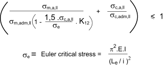
Timber members pinned at both ends which are subject to bending and axial
compression should be so proportioned that:

Spaced Columns
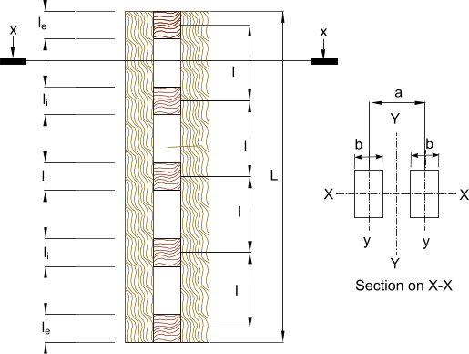
Spaced comumns are two or more equal parallel columns used together as supports and
spaced using packing blocks as shown below. These composite arrangements can be used individually or as component
parts of lattice girders.

L = overall length of columns (m)
l e = thickness of end packing pieces (m)
l i = thickness of intermediate packing pieces (m)
l = pitch packing pieces (m)
a = centre distance between component columns (m)
b = column thickness (m)
End packing.
The end packing length le should be sufficient to accommodate the nails, screws
or connectors required to transmit, between the abutting face of the packing and
one adjacent column, a shear force equal to:

A = Total cross section area of column (m2)
l e = thickness of end packing pieces (m)
n = number of columns
The spacing of the columns should be less than 3 x the thickness of the thinner column.
Intermediate packing.
The length of the intermediate packs l i must be at least 230mm . Also the connecting methods should be designed
to transmit at least 50% of that force required for an end pack.i.e the shear forc to be resisted =

The spacing of the columns should be less than 3 x the thickness of the thinner column.
For cases where L=< 30b then only intermediate packing is required.
In any event, sufficient packings should be provided to ensure that the slenderness ratio (Le/ i )1C of the local portion of an individual shaft between packings is limited to
either 70, or to 0.7 times the slenderness ratio of the whole column, whichever is the lesser. Lefor the local part should be based on the distance between the packing centroids

Load Capacity
The load capacity of a spaced column is calculated as the least of the following.
Bending about X-X axis...Axial capacity = ( Total column Area.) x ( σc,adm,ll)
Bending about Y-Y axis.....Axial capacity = ( Total column Area.) x ( σc,adm,ll)
where the effect length Leyy is assessed in accordance with the diagram above and multiplied by
K13
Individual buckling.....Axial capacity = (n x area of one column) x ( σc,adm,ll)
where the effective length Le is the length between packings and the rzdius of gyration i
iy for the y-y axis of a single column.
| Connection | K13 |
| Ratio of space to thickness of thinner member |
| 0 | 1 | 2 | 3 |
| Nailed | 1,8 | 2,6 | 3,1 | 3,5 |
| Scewed/bolted | 1,7 | 2,4 | 2,8 | 3,1 |
| Connectored | 1,4 | 1,8 | 2,2 | 2,4 |
| Glued | 1,1 | 1,1 | 1,3 | 1,4 |
Tension Members
The permissible stress for members subject to tensile loads provided in the tables are generally
based on solid timber with a width of 300mm. For members with width other than 300m a factor K14 must
be applied. ref K14.
A timber member subject to direct tensile load is simple simply sized by ensuring the actual stress is less than the admissible stress
calculated using the appropriate grade stress and modifying factors where applicable
- K2 relates to the moisture content of the timber
- K3 relates to the duration of the load.
- K6 relates to the shape of the cross section.
- K8 relates load sharing factors.
- K14 relates to the depth of the section
|
Therefore
σt.adm,ll = σt.g. K2.K3.K6.K8.K14
σt ≤ σt.adm,ll
σt,ll = Calculated tensile stress parallel to grain
σt.adm,ll = Admissible tensile stress parallel to grain
σt.g,ll = Grade tensile stress parallel to grain
For members subject to combined bending and axial tensile the following equation applies

|


