Introduction
The notes below are basic guidance notes showing the spacings and permissible loads for nails,woodscrews,bolts and adhesives
whan fastening timber beams together. The information is generally based on data included in BS 5268-2:2002
The tables below show only a small part of the comprehensive
data provided in the identified standard. The information is intended to indicate the level
of permissible stresses which may be considered for type of connections shown. For detailed design
of timber structures it is important that the relevant standards and codes are used.
Notes relating the strength grade to the wood species are found on webpage Timber Design
Relevant Standards..For comprehensive list of standards Wood related Standards
BS 5268 -2 ;2002 Structural use of timber � Part 2: Code of practice for permissible
stress design, materials and workmanship
BS EN 1912:2004: Structural timber
Strength classes- Assignment of visual grades and species
Symbols
d = the fixing item diameter.(mm)
F = Basic shear load of component as tabled (N)
Fadm = Permissible Load (N)
K = Factor related to number of nails,or loading condition
Ns = Number of shear planes sharing load
n = number of fixings
a = distance (m)
α = angle of grain (deg /rads)
A = Area (m2)
b = breadth of beam/thickness (m)
E = Modulus of Elasticity (N/m2
Emean = mean value Modulus of Elasticity (N/m2
Emin = min value Modulus of Elasticity (N/m2
G = Modulus of Rigity (N/m2 /Pa
h = depth of section (m)
i =radius of gyration (m)
I = Second Moment of Area (m4
L =Length /span/ (m)
Le =Effective Length /Effective span (m)
m = mass (kg)
n = number
λ = slenderness ratio
Q = First moment of area(m3
ρaverage = average density (kg / m3)
M = Moment (Nm)
σm.a,ll = Applied bending stress parallel to grain (N/m2)
|
σm.g,ll = Grade bending stress parallel to grain (N/m2)
σm.adm,ll = Permissible bending stress parallel to grain (N/m2)
Fv = Applied shear Force (N)
τm.a,ll = Applied shear stress parallel to grain (N/m2)
τm.g,ll = Grade shear stress parallel to grain (N/m2)
τm.adm,ll = Permissible shear stress parallel to grain (N/m2)
τr.a,ll = Applied rolling shear stress parallel to grain (N/m2)
τr.adm,ll = Permissible rolling shear stress parallel to grain (N/m2)
Δm = bending deflection (m)
Δs = shear deflection (m)
Δtotal = total deflection (shear + bending) (m)
Δadm = pemissible deflection (m)
σc.a,ll = Applied compressive stress parallel to grain (N/m2)
σc.g,ll = Grade compressive stress parallel to grain (N/m2)
σc.adm,ll = Permissible compressive stress parallel to grain (N/m2)
σc.a,l- = Applied compressive stress normal to grain (N/m2)
σc.g,l- = Grade compressive stress normal to grain (N/m2)
σc.adm,l- = Permissible compressive normal parallel to grain (N/m2)
σt.a,ll = Applied tensile stress parallel to grain (N/m2)
σt.g,ll = Grade tensile stress parallel to grain (N/m2)
σt.adm,ll = Permissible tensil stress parallel to grain (N/m2)
|
The notes below are basic guidance notes showing the spacings for nails,woodscrewsa and bolts
whan fastening timber beams together.
Nails
The values identified in the table below relate to nails made from wire driven at right angles to the grain. For the loads given here for nails to be valid, the steel wire from which the nails are produced should have
a minimum ultimate tensile strength of 600 N/mm2 In hardwood
the holes normally need to be pre-drilled with diameter not bigger than 0,8 d.
Figure showing minimum Nail spacing
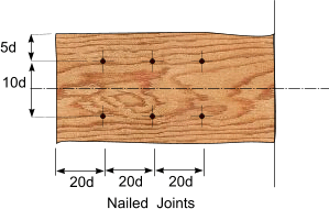
Note: The spacings between nails as shown can be reduced for all softwoods, except Douglas fir, by 0,8. The edge spacings shown must be at least 5d.
The permissible loads for nail joints in service class 1 and 2 joints are derived from the equation
Fadm = F . K. . n . Ns.
In the standanard K = K43.K46 K48.K49.K50.
K43 = 0.7 for nails driven into the end grain otherwise = 1,00.
K46 = 1,25 for nails driven fastening a predrilled steel component to a timber member the hole in the steel member should not be greater than d.
K48 = 1,00 for long term loading for timber to timber joints, 1,12 for medium term loads, 1,25 for short/very short term loading
{1.40 for particleboard-to-timber joints: medium-term loads & 2,1 for particleboard-to-timber / OSB-to-timber" joints: short/ very short term loading}
K49 = 1,00 in service classes 1 & 2 and 0,70 for service class 3
K50 = 1,00 when n l =< 10 and = 0,9 when n l > 10......n l
= number of nails in any line of nails parallel to applied load
For softwoods where the thicknesses of members or nail penetrations are
less than the standard values given in the table below, the basic load should be multiplied by the smaller of the two ratios: (see tables below)
a) actual to standard thickness of headside member;(see tables below) or
b) actual penetration to standard pointside thickness.(see tables below)
If either ratio is less than 0,66 then the joint is assumed to have no load carrying capacity
Table of basic shear loads (F) for nails in timber to timber joints
| Nail dia | Softwoods ***
Not predrilled | Hardwoods
pre-drilled |
Standard
Thickness/
Pentration | C14 | C16/18/22 | C24 | C30,35,40 | Min. Pentration | D40 | D50 |
| mm | F (N) | F (N) | F (N) | F (N) | mm | F (N) | F (N) |
| 2,7 |
32 |
249 |
258 |
274 |
281 |
22 |
386 |
427 |
| 3 |
36 |
296 |
306 |
326 |
335 |
24 |
465 |
515 |
| 3,4 |
41 |
364 |
377 |
400 |
412 |
27 |
582 |
644 |
| 3,8 |
46 |
438 |
453 |
481 |
495 |
30 |
709 |
785 |
| 4,2 |
50 |
516 |
534 |
567 |
583 |
34 |
897 |
939 |
| 4,6 |
55 |
600 |
620 |
659 |
678 |
37 |
996 |
1103 |
| 5 |
60 |
689 |
712 |
756 |
778 |
40 |
1155 |
1279 |
| 5,5 |
66 |
806 |
833 |
885 |
910 |
44 |
1368 |
1515 |
| 6 |
72 |
930 |
962 |
1022 |
1051 |
48 |
1595 |
1767 |
| 7 |
84 |
1200 |
1240 |
1318 |
1355 |
56 |
2094 |
2319 |
| 8 |
96 |
1495 |
1546 |
1643 |
1689 |
64 |
2649 |
2933 |
*** For predrilled holes in softwood the values in table may be multiplied by 1,15 .
Screws
Screws should be turned, not hammered, into pre-drilled holes. The tops of countersunk screws should be no more than 1 mm below the surface of the timber.
The values provided for the screws are for screws in accordance with BS 1210 in predrilled holes.
The holes should be drilled with the screw shank dia. for the part of the hole which
relates to the screw shank, reducing to a pilot hole dia = d/2 for the threaded portion
of the screw.
The effective cross-section of timber taking a load be determined by deducting the net
projected area of the pre-drilled holes from the gross area of the cross-section being considered.
When assessing the effective cross-section of multiple screw joints, all screws that lie within a distance of
five screw diameters measured parallel to the grain from a given cross-section should be considered as
occurring at that cross-section.
The permissible loads for nail joints in service for class 1 and 2 joints are derived from the equation
Fadm = F . K. . n . Ns.
In the standard K = K43.K46 K52.K53.K54
K43 = 1,0 for screws normal to grain direction/ = 0.7 for screws screwed into the end grain.
K46 = 1,0 for timber ot timber joints/ 1,25 for screws fastening a predrilled steel component to a timber member the hole in the steel member should not be greater than d.
K52 = 1,00 for long term loading for timber to timber joints:1,12 for medium term loading:1,25 for short term loading
K53 = 1,00 inservice classes 1 & 2 and 0,70 for service class 3
K54 = 1,00 when n l =< 10 and = 0,9 when n l > 10......n l = number of nails in any line of nails parallel to applied load
For the basic loads the table to apply, the headside member thickness and the penetration of
the screw in the pointside should be not less than the values given.
Where the thickness of the headside member is less than the value given in the table, the tabulated basic
load should be multiplied by the ratio of the actual to the standard headside thickness, provided that the
pointside screw penetration is at least twice the actual headside thickness. The minimum headside
member thickness should be not less than twice the shank diameter.
Figure showing minimum screw spacing
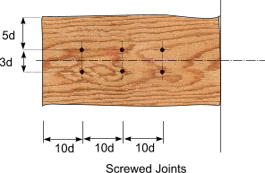
Table of basic shear loads (F) for screws in timber to timber joints
| Screw shank dia |
Penetration |
Softwoods
pre-drilled | Hardwoods
pre-drilled |
| Headside |
Pointside |
C14 |
C16/18/22 |
C24 |
C27/30/35/40 |
D30/35/40 |
D40/60/70 |
| mm |
mm |
N |
N |
N |
N |
N |
N |
| 3 |
11 |
21 |
193 |
206 |
233 |
243 |
308 |
355 |
| 3,5 |
12 |
25 |
264 |
282 |
306 |
317 |
399 |
459 |
| 4 |
14 |
28 |
338 |
361 |
392 |
406 |
515 |
594 |
| 4,5 |
16 |
32 |
432 |
453 |
488 |
506 |
643 |
744 |
| 5 |
18 |
35 |
524 |
550 |
594 |
616 |
785 |
910 |
| 5,5 |
19 |
39 |
621 |
647 |
698 |
724 |
921 |
1065 |
| 6 |
21 |
42 |
729 |
760 |
821 |
851 |
1086 |
1259 |
| 7 |
25 |
49 |
968 |
1010 |
1092 |
1133 |
1454 |
1690 |
| 8 |
28 |
56 |
1094 |
1170 |
1309 |
1359 |
1760 |
2056 |
Bolts
The values for bolted joints relate to BS EN ISO 898-1 having a minimum tensile strength of 400 N/mm2
with washers which conform to BS 4320 . Bolt holes should not be drilled more than 2mm larger than
the nominal bolt diameter. Washers should have a diameter or width of three times the bolt diameter with
a thickness of 0,25 times the bolt diameter and should be fitted under the head and nut of each bolt unless a
steel plate is used to provide an equivalent bearing area.
At least one complete thread should protude above the tightened nut.
The effective cross-section of the timber taking loads should be determined by deducting the
net projected area of the bolt holes from the gross area of the timber cross-section. All bolts that lie within a distance of two
bolt diameters, measured parallel to the grain, from a given cross-section should be considered as occurring
at that cross-section.
The permissible load for a bolted joint for Ns shear planes
Fadm = F . K. n . Ns.
In the standard K =K46. K56.K57
K46 = 1,00 for normal timber to timber joints/ =1,25 Where a steel component is bolted to a timber member loaded parallel to the grain.
K56 = 1,00 in service classes 1 & 2 / = 0,70 for service class 3 timber used in that service
K57 = 1 - 3( n l - 1)/100 when n l =< 10 and = 0,9 when n l > 10....n l
= number of in-line bolts in any line parallel to applied loads.
Figure showing minimum Bolt/Dowel spacing
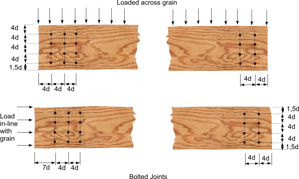
Table showing single shear loads for one grade 4,6 bolt in a two member timber connection
Important Note: The table below shows only a selected number of bolt diameters subject to long term loading
| Timber Grade |
Penetration |
Loading Parallel to grain | Loading perpendicular to grain |
| mm |
kN |
kN |
kN |
kN |
kN |
kN |
kN |
kN |
Min Thickness |
M8 |
M12 |
M16 |
M20 |
M8 |
M12 |
M16 |
M20 |
| C16 |
47 |
1,22 |
1,80 |
2,30 |
2,73 |
1,13 |
1,56 |
1,91 |
2,19 |
| |
72 |
1,46 |
2,68 |
3,52 |
4,19 |
1,39 |
2,39 |
2,93 |
3,36 |
| |
97 |
1,46 |
3,13 |
4,63 |
5,64 |
1,39 |
2,79 |
3,94 |
4,52 |
| C24 |
47 |
1,33 |
2,04 |
2,59 |
3,09 |
1,23 |
1,76 |
2,16 |
2,47 |
| |
72 |
1,55 |
2,93 |
3,97 |
4,73 |
1,47 |
2,64 |
3,30 |
3,79 |
| |
97 |
1,55 |
3,42 |
5,05 |
6,37 |
1,47 |
3,07 |
4,43 |
5,11 |
| D40 |
47 |
1,83 |
3,08 |
3,92 |
4,67 |
1,83 |
3,08 |
3,92 |
4,67 |
| |
72 |
1,91 |
4,02 |
5,98 |
7,16 |
1,91 |
4,02 |
5,98 |
7,16 |
| |
97 |
1,91 |
4,21 |
6,93 |
9,32 |
1,91 |
4,21 |
6,93 |
9,32 |
| D50 |
47 |
2,12 |
3,78 |
4,81 |
5,73 |
2,12 |
3,78 |
4,81 |
5,73 |
| |
72 |
2,12 |
4,66 |
6,92 |
8,78 |
2,12 |
4,66 |
6,92 |
8,78 |
| |
97 |
2,12 |
4,66 |
8,09 |
10,82 |
2,12 |
4,66 |
8,09 |
10,82 |
The above show load which act perpendicular to the
axis of the bolt, and parallel or perpendicular to the grain of the timber
Adhesive joints
The adhesive used should be appropriate to the environment in which the joint will be used. the table below
identifies some adhesives which are acceptable.
If the timber is correctly specified and the manufacturing process is to an acceptable standard then the adhesive
is always stronger than
the timber used and the strength of the joint is based on the weaker of the timber joint components being glued.
The load duration factors and the load sharing factors apply in determining the acceptable strength of the joint.
It is important to note that adhesive joints are primarily shear loaded joints. Tensile components of stress perpendicular to the plane of the glueline
are not acceptable.
| Intended Use | Exposure Conditions | Typical exposure | Adhesive type | Exterior | High Hazard | Full weather exposure with exposed gluelines
Oly Laminated timbers should be used for this application | Phenolic/ aminoplastic adhesives
satisfying spec'n of type I
in accordance with BS EN 301 |
| Exterior | Low Hazard | Protected from weather and roofs of non important structures | Phenolic/ aminoplastic adhesives
satisfying spec'n of type I or type II
in accordance with BS EN 301 |
| Interior | High Hazard | Damp locations, unventilated
loft spaces, chemical works Laundries | Phenolic/ aminoplastic adhesives
satisfying spec'n of type I
in accordance with BS EN 301 | Interior | Low hazard | Heated and ventilated areas | Phenolic/ aminoplastic adhesives
satisfying spec'n of type I or II
in accordance with BS EN 301 |
The relevant section in BS 5278 part 2 is limited to the type of structural joints as shown below
When considering adhesive joints in timber the risk resulting from shrinkage, distortion and stress
concentration at the joint should be considered.
The glued faces are normally held together until the glue sets and surface force of
about 0,7 N/mm is recommended for softwoods If mechanical fasteners are used to hold the glued
faces together these should not be considered to add strength to the bonded joint. When nails are used
to hold the glued faces together the permissible shear stength used in the calculations should be multiplied by a nail/glue
modification factor K70 = 0,9
A typical glued timber joint withstanding a force F is shown below.
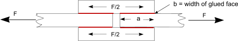 . .
When the components of the joint are loaded
parallel to the grain, the permissible shear stress fot the bonded lap joints should be taken as the lesser of the
permissible shear stresses parallel to the grain. When one of the faces is loaded at an angle to the relevant
grain α, the permissible shear stress τ adm,a for the glueline
should be calculated using the following equation.

When one of the faces is loaded across the grain the the permissible stress is 1/3 of the permissible grade
shear stress parallel to the grain. In this circumstance the shear is referred to as rolling shear because
there is a tendency for the fibres to roll like a rolling cylinders at alower stress level
For the loaded lap joint system as shown above the permissible force Fadm.a =
 .. ..
( ref to Page Modifying factors )
This equation is based on forces parallel to the grain and the surfaces being clamped to achieve adhesive
bonding. If nails are used to hold surfaces together to achieve good adhesive bonding then the equation below should be used.

|